Affichage des articles dont le libellé est lightwave3d. Afficher tous les articles

lundi 26 octobre 2009

Lightwave 3D Beginners Guide

Introduction

Welcome to the Lightwave 7.5 Beginners Guide! This Guide is only an update from my Lightwave 6.5 Beginners Guide to suit Lightwave 7.5; the content is pretty much the same, however, a few new additions has been made in the Tutorial section. We will start out with an introduction to 3D in general, and if you feel that you know the basic concepts already, you can simply skip this part and dive directly into the Lightwave Parts. The best way to get to know the Interface and how tools work is to use them, and tutorials are great for this purpose, so we will be doing a tutorial as I explain the bits and pieces of Lightwave.

An Introduction to 3D

I'd say that the most important thing you need when you want to create 3D art is your imagination, a picture in your head of how you want it to turn out. Your choice of 3D software doesn't really matter, since it always comes out to the artist and how creative one can be. All 3D programs are based on the same idea, where you build up your scenes with Objects, and Objects are built up by Points and Polygons. Take a look at the two pictures below, it's just a box right? Well this is an object, a very simple one, but still an object.
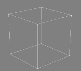
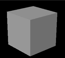

As you can see in Picture 1, there's a point in each corner of the box. Picture 2 on the other hand shows the Polygons, and these are the ones you give materials to, and they are the ones you will see in the final render. I guess you already knew that 3D stands for 3Dimensional, and this is what you work with in any 3D program out there. In Lightwave, these Dimensions are called X, Y and Z, and these could be described as Left/Right, Up/Down and Near/Far respectively.

What's the advantage of using a 3D program then? Well, you can create nice artwork by drawing them in a 2D program, but when it comes to animating what you've created it becomes a bit harder, and this is where the 3D program has an advantage. Another thing to mention is that you can change anything in the pictures you create. If you didn't like the material on a certain object, or if the light setting was wrong, just change it and re-render.

That'll do for an introduction; lets get going with Lightwave!

The Basics of Lightwave

Follow the installation instructions and install Lightwave on your harddrive. Lightwave comes as two separate programs, Lightwave Layout and Lightwave Modeler, and from now on they will just be referred to as Layout and Modeler.

Lightwave Layout

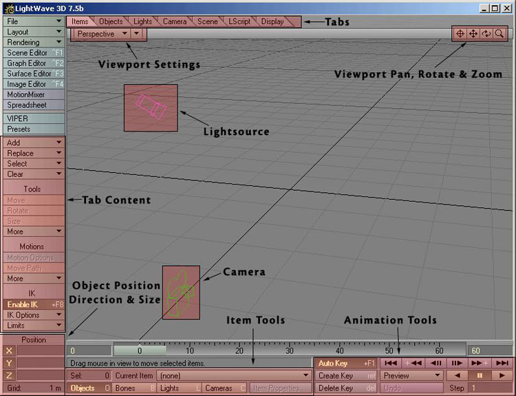
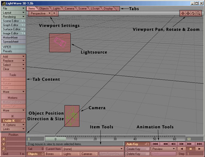
If you start Layout up it should look something like picture 3.
Click to enlarge
Picture 3: Lightwave Layout (Click to enlarge)

This is where you load objects you've created, give them textures, edit lights & cameras, animate things and render your final pictures. As you can see I have added a few descriptions on some of the items in picture 3. However, we will not start the tour in Layout, but we will get back to it later on in the Guide.

Lightwave Modeler

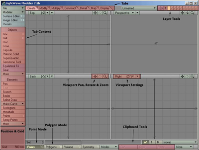
If you load Modeler up, it should look something like picture 4.
Click to enlarge
Picture 4: Lightwave Modeler (Click to enlarge)

The Modeler lets you model all the necessary objects you need for your scene. You also prepare your objects for Layout here, like attaching surfaces to them etc. I put a few descriptions on picture 4 as well, and we will get to know the interface better next.

Getting to know Modeler

We'll start with a few explanations on how Lightwave is built up, and then we'll start the main tutorial and learn the tools we use as we go along.

The Interface & Workflow

The Workflow is one of Lightwave's stronger areas. If you look at the Interface, you'll see that every Tool or Button is named with text. No image buttons that takes ages to learn, plus that the interface is very clean. You also have shortcuts on your keyboard for almost every Tool in Lightwave. The menus are also configurable and you can create your own menus to fit your own needs.

Keyboard Shortcuts

If you look at the "Box" Tool button in the "Create" Tab, you'll see that in the right side of the button there's an "X". This means that a capital X is the shortcut key for the Box Tool, so if you hit "shift+X" on your keyboard, you'll see that the Box Tool gets activated. This is how it works with all the other Tools that have a key assigned to them as well.

If you would like to assign a shortcut to a Tool that perhaps doesn't have one, hit "alt+F9" on your keyboard and you will get a list over all the Tools available, and a list over all the keys on your keyboard. You can also access certain setting panels from the "Modeler" pull-down menu at the top left of Modeler.

Plugins

Lightwave comes with lots of Plugins that you need to get things working properly. We will start by installing these in Modeler. At the top left of the Modeler window, you should see a button named "Modeler". If you click this one with your Left Mouse Button, you will get a small menu with a few sections and options. One of the sections is named "Plug-ins", so click that one and a sub-menu will appear. From this sub-menu, select "Edit Plug-ins".

A Panel will appear and this is where you control your Plugins. If you didn't install your Plugins already, we will do it now. Click the "Scan Directory" button on the right of this Panel, and a browser window will appear. Browse to your Lightwave Directory (on your harddrive) and find the Folder named "Plugins", simply just mark this Folder and click OK. Lightwave will now install all the Plugins it will find automatically. When it's done you can simply close down the Plug-ins Panel.

Display Options

Modeler has got four Viewports by default. Each of these Viewports can have their own unique settings. Open up the Display Options panel by hitting "d" on your keyboard, it should look something like picture 5.
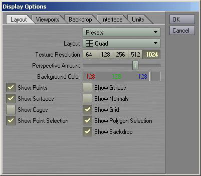
Picture 5: Display Options Panel

The first tab called "Layout" in this panel contains a few global settings. This means that if you change something here it will take place in all of the Viewports. As you can see I've turned off a few options here, and this is just my own preference. What we will change though, is the Top Right Viewport (Perspective View) and how that one should appear. So to edit just one of the Viewports, click the "Viewports" Tab. The first thing to do here is choose which of the Viewports we want to edit, so click on the "TR" (Top Right) button to select that one, then use the options that picture 6 are showing.
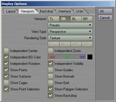
Picture 6: The settings for the Top Right Viewport

Once you've entered all the settings here, just click OK to save it, and if you look at the perspective view now, it should look something like picture 7.
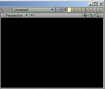
Picture 7: The Top Right View/The Perspective View

There are a few more things we are going to change in the Display Options Panel, so hit "d" once more to bring it up again. Click the last Tab - "Units", then use the settings shown in picture 8.
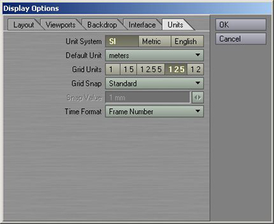
Picture 8: The Units settings

Once you're done with these settings, click OK again to save the changes.

Each Viewport has got a Pan, Rotate and Zoom Tool, and a variety of render modes, picture 9 shows the Toolbar for one of the Viewports.
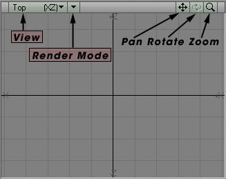
Picture 9: Viewport Tools

As you can see on picture 9, this view is set to "Top XZ", but you can easily change it to any of the others by using this pull-down menu. Just to the right of the View menu you can select what type of Render Mode you wish to use for that view, such as Wireframe, Smooth Shaded and so on. The Pan Tool lets you Pan the Viewport, and if you prefer to use the mouse and keyboard, just hold down the "Alt" key while you click inside the view with your Left Mouse Button and drag it around. The Rotate Tool only works in the Perspective View. In any Perspective view you have, you can also hold down the "Alt" key while dragging in the view, which will work as a Rotate Tool. The Zoom Tool will zoom in or out using the centre of the view as a target.

Modes & Tools

At the bottom of Modeler, you should see two buttons named "Points" and "Polygons". These are the two modes of Modeler, and will give you more control over what you are doing when you model your objects. If you read the first part of this Guide then you should know what Points & Polygons are, otherwise, move back and read it. It is essential that you know what Points and Polygons are if you want to get anywhere with modelling.

The Tools that come with Modeler, has been nicely categorised under the Tabs, just above the Top Left Viewport. The "Create" Tab is open by default when you load Modeler, and if you click any of the other ones, you should see that the Tools to the left of Modeler changes. To activate a Tool, simply click on it once. Activate the Box Tool in the "Create" Tab now. If you move your mouse over any of the Viewports now you can see that the mouse pointer has turned in to a small 3D box. The same thing happens with the other Primitive Object Tools, the Ball Tool turns into a small ball, the Disc Tool into a small cylinder and so on. To Deactivate a Tool simply click it again or hit "Space" on your keyboard. We are going to go through the most common tools a bit later in this Guide, to get to know them better.

The Numeric Panel

Almost every Tool in Modeler comes with a Numeric Panel. This panel lets you enter exact values of how you want the final result to turn out. For example, using the Numeric Panel when you have the Box Tool activated lets you enter exact values of how big the box should be, and if you're using it when you have the Move Tool activated, you can enter an exact value as to how much you want to move the object and so on.

Activate the Box Tool and hit "n" on your keyboard. Once you hit "n" the Numeric Panel will come up showing you default values of the Tool you selected, in this case the Box Tool. Once you activated the Numeric Panel, a box was created in real-time in the ViewPorts of Modeler, and as you make changes in the Numeric Panel, it will affect the Box in the ViewPorts. Close down the Numeric Panel by clicking "n" once more (or by clicking the "X" at the top right of the Numeric Panel window), and then hit "Space" on your keyboard to deactivate the Box Tool and to create the Box. Don't delete this box; we'll need it later on.

The Hub

The Hub is what Lightwave uses to communicate between the Layout and the Modeler. When you've finished modelling your objects for instance, simply send them to layout via the Hub. This increases the workflow even more, and makes Lightwave more like one program instead of two. As soon as you start Lightwave up, the Hub will automatically start running, you'll notice a small green icon in the System Tray. If you don't have enough ram in your machine, and Lightwave tends to get slow after a whiles usage, then you can turn the Hub off via the System Tray, its requirements are pretty high.

If you would like to run without the Hub permanently, then do the following steps. Add two shortcuts to Layout and Modeler in your Windows hotbar (down where the Start menu is). Right click the Layout shortcut and select Properties. In the Window that comes up, you should have a "Target" string, indicating where on your harddrive the executables are. In the end of this string, add "-0", making it look something like:

...Newtek\Programs\Lightwav.exe -0

Do the same with the Modeler shortcut, and the next time you run either of them, the Hub will not start automatically, saving you lots of RAM.

Objects & Layers

You can have many objects loaded at the same time in Modeler, and just above the Top Right Viewport you should see a pull-down menu where it currently says "Unnamed". This is the object you are working on at the moment, and if you have more than one object loaded in Modeler, you can switch to which one you wish to work with here.

To give you even more control over your objects while you work with them, Modeler brings you Layers. Each object can have 990 layers, and this is more than plenty. Just above the Top Right Viewport you should see 10 small boxes, and these are the layers. Picture 10 shows the Layer Tools.
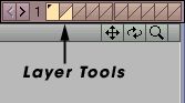
Picture 10: The Layer Tools

The one to the very left is lit up with a yellow colour, which means that it is active. As you can see there's a little black dot in this Layer. Remember the Box we created earlier? Well, the little black dot indicates that this layer has got an object in it.

If you look at picture 11 you will see that each of these boxes is divided in two. The Top part indicates Foreground Layer, and the Bottom part indicates Background Layer.
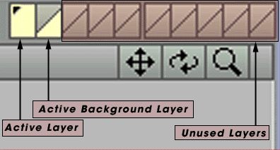
Picture 11: A Closer look on the Layers

One of the new things since LW6.5 are the Layer Groups. Earlier you could only have 10 layers per objects, but with this feature you can have 990. 10 Layers per group and a total of 99 groups. Picture 12 shows the Layer Groups.
Picture 12: The Layer Groups

Lightwave Universe

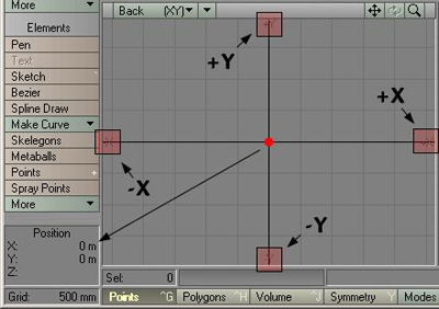
Both Modeler and Layout has something called Lightwave Universe, and the Universe has got a centre spot. As you can see in the four views of Modeler, there are two lines in the grid pattern that are a bit thicker than the others. Where these two meet, that's the exact centre. The values for X, Y and Z here are all zero.

Working in the Bottom Left Viewport, put your mouse pointer at the exact centre and watch the Position Window. It should look something like picture 13.
Picture 13: Closer look at the Axes

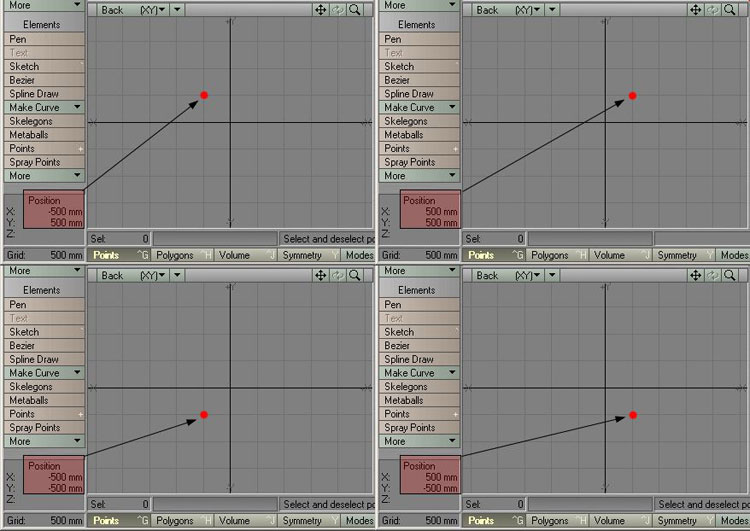
The red dot in the middle of the View indicates the centre of the Universe, and as you can see in the Position window, the values are both zero there. The picture also shows that each axis has got a negative and positive side. In my example I'm using the "Back" View, or the Bottom Left Viewport, and this viewport shows the X and Y axis. Left of the vertical centre line you have the negative X, and on the right you have the positive X. Below the horizontal centre line you have the negative Y, and above you have the positive Y. Does it sound hard? Well, I've made a few pictures to ease things up a bit.

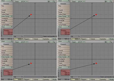
Picture 14 shows 4 different positions for the mouse pointer, which is indicated by the little red dot. Note that the Grid Size is set to 500mm, and therefore each square in the grid pattern indicates 500x500 millimetres of space.
Click to enlarge
Picture 14: 4 different positions for the mouse pointer (Click to enlarge)

All of the views in picture 14 show the Back View (Bottom Left Viewport), and you can try this out yourself by just moving your mouse pointer in the Viewport.

There you have some information on how Modeler is built up and how things work in general. We will now start the main Tutorial, and while we go along we will do a few smaller tutorials on the tools we use etc.

Create a Glass Bowl using lightwave 3d

Okay, lets start using Lightwave for real then. Keep your Modeler running, and to the top left, click the "File" pull-down menu and select "Close All Objects". This will clear the Modeler so we can start over with our new project. In our first Tutorial we will be creating a Glass Bowl, and here are some of the things you get to learn and use.

Box Tool
Pen Tool
Lathe Tool
Flipping Polygons
Assigning Surfaces
Basic Subpatches
Using Layers
Glass Materials
Reflective Materials
Basic Camera Settings
Basic Light Settings
Basic Rendering Options


Picture 15 shows the final render:

Click to enlarge
Picture 15: The final Glass Bowl Picture (Click to enlarge)

The Bowl Shape

We are going to use the Pen Tool to create an outer shape of the bowl, but before we do this, we need to adjust the Modeler. In the Bottom Left Viewport, change the View to "Back (XY)" if it isn't already, then place your mouse pointer in the centre of all four views and drag it up to the right. This will increase the size of the "Back" view and we will have more control over what we do. Use the Pan tool in the Back Viewport and drag until the centre of the universe is at the bottom left, look at Picture 16 and you'll know what I mean.

Click to enlarge
Picture 16: Prepare the Modeler (Click to enlarge)

Now how do you set the grid size to 10mm then? Well, it's quite simple. When you use the "Zoom" Tool, Modeler will automatically adjust the grid size whether you zoom in or out. In the Back View, click the "Zoom" button and drag with your mouse to zoom in. Keep an eye on the Grid Size as you do this, because you'll notice that the Grid Size changes. So zoom in until the grid size says "10mm". Have a look at picture 16 again to see what it should look like.

The Pen Tool

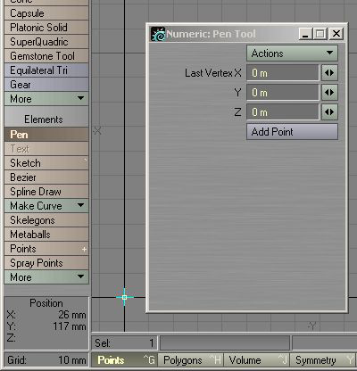
The Pen Tool is quite simple to use. It lets you place points, and as you do it also connects the points with polygons. Like many of the other Tools in Modeler, the Pen Tool comes with a Numeric Panel, which lets you insert exact values on where the points should be created. Activate the Pen Tool now, you'll find it in the "Create" Tab. Once activated, press "n" on your keyboard to bring up the Numeric Panel. As you can see in the Numeric Panel, the default values for all the axis are set to zero, and if you look at the centre of the Universe in the Back View, you should notice that a point has been placed there, like in picture 17.

image01
Picture 17: The Numeric Panel for the Pen Tool

The first point has been created, so close down the Numeric Panel now by clicking the "X" at the top right of the Panel, but keep the Pen Tool activated.

We will use the Pen Tool to place points in the shape we want the Bowl to be, and as we place our points, Modeler will connect them with polygons automatically. I used a total of 29 points for my shape, and you can use more or less for your shape if you want to.

Have a look at picture 18; you'll see that I've numbered each point in which order I created them, so try to create a similar shape now.

Click to enlarge
Picture 18: The Basic Bowl Shape, try to create a similar shape (Click to enlarge)

Deselect the Pen Tool once you're done creating the shape. I created my points in a clockwise order, and this will result in that the polygons will face inwards later on when we lathe it. Does it sound complicated? Lets have a look at the lathe tool and you'll know what I mean.

The Lathe Tool

Now size down the Bottom Left Viewport until all four Viewports are the same size. If you press "a" on your keyboard now, the shape we have created will be fitted nicely in all four Views as well. Picture 19 shows what we have so far.

Click to enlarge
Picture 19: The basic Glass Bowl shape (Click to enlarge)

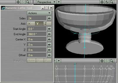
Click the "Multiply" Tab and then activate the "Lathe" Tool by clicking on it. We are going to have a look at the Numeric Panel here as well, so press "n" on your keyboard to bring it up. Once the Numeric Panel came up, a real-time preview of the Bowl appeared in the Viewports. As you can see in the Perspective View now, the polygons of the bowl are facing inwards, like I mentioned earlier. We can fix this easily by flipping the polygons later on when we're done lathing. So how does the Lathe Tool work then? Well it's quite simple. It takes the 2D polygon shape we created, and it spins it around 360 degrees, and while it spins it, it creates geometry out of what the 2D polygon shape looks like.

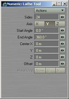
Lets have a closer look at the Numeric Panel then. The amount of sides determines how many times the 2D polygon shape should be duplicated when it spins it. The default value is 24, which will do fine for this bowl. The centre values should all be set to zero, since that's where we started creating the polygon shape.

The Start and End Angle determines where it should start spinning, and where to stop. Picture 20 shows an example of this.

image02image03
Picture 20: Testing the Angle values

Picture 20 is divided into two. The picture to the left shows a value of 180 degrees entered for the End Angle, making the lathe tool only create half of the Bowl. Using 360 degrees like in the picture to the right will spin it all around making the Bowl complete.

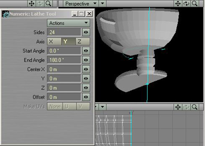
So the final settings for the Lathe Tool should be what picture 21 shows.

image04
Picture 21: The settings for the Lathe Tool

When you've entered these settings, just close down the Numeric Panel and hit Space to perform the operation, then press "a" to fit the Bowl in the Viewports. When you're done with that, press "f" to flip the polygons and we're done!

Assigning Surfaces

What we want to do now is give this Glass Bowl a material. The final surfacing and the creation of the glass material will be done in Layout later on, and right now all we have to do is assign a name to the Glass Bowl. Press "q" on your keyboard to bring up the "Change Surface" panel. Name this surface "Glass Bowl", set the Specular to 50% and click the "Smoothing" button (to activate it), then just click "OK" to apply the changes.

The Glass Bowl is looking a bit rough at this point, but we will take care of that next.

Subpatches

Lightwave can turn objects into Subpatches, which will smooth the polygons out. Then when the sides of the object are smooth, we freeze the Subpatches and the object gets a new smooth shape permanently. Make sure everything is unselected in Modeler, and then hit "Tab" on your keyboard to turn the object into a Subpatch. Notice how smooth the bowl turned out? It should look something like picture 22 at this moment.

Click to enlarge
Picture 22: Subpatches activated (Click to enlarge)

Now we want to tell Modeler how much it should smooth the polygons. If you hit "o" on your keyboard an Options Panel will open up. You can set various settings here but at the moment we are only interested in the "Patch Division" setting. We will use a Division of 3 here so enter that number in the "Patch Division" field. This means that each Patch in our mesh will be subdivided 3 times when we freeze it. Click OK to close down the Options Panel, and then hit "ctrl+d" on your keyboard to freeze the Subpatches.

The object is now back in to a polygon mesh.

Now I need to say something about surfaces and how they work in Lightwave. As you might know, light bends when it passes through transparent materials such as glass. At this point, our bowl only has polygons facing outwards, meaning it wont appear as solid glass once we render it, know what I mean? If we were to create an inside of this bowl, then Lightwave would know that the glass is solid and it will know when to start and stop bending the light. We can fix this quite easily, all we need to do is to copy the polygons of the bowl, paste them in a new layer and then flip them so that they're facing inwards. Then we will have an outside and an inside for our bowl.

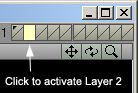
Make sure everything is unselected and hit "c" on your keyboard to copy this bowl object. Now it's time for us to use the Layers. If you look at the 10 small boxes up to the right, you'll notice that black little dot I was talking about earlier in Layer 1 (the box to the very left). This means that that Layer is taken, and we know it is, by our bowl object. Activate Layer 2 now by simply clicking in the upper part of the box; it should look like picture 23.

image05
Picture 23: Layer 2 active

Once you click on Layer 2, the bowl object will disappear from the four Viewports. We have a new empty work area for our next procedures, and anything we do in Layer 2 will not affect Layer 1 where the bowl is. Paste the object in by hitting "v" on your keyboard, we now have a second bowl which will become the inside for our main bowl.

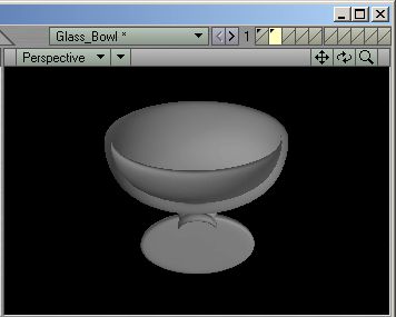
Hit "f" on your keyboard now. This will flip all the polygons in our object, making them face inwards instead of outwards. We just need to give this object a new Surface and we are done, so hit "q" on your keyboard again and the "Change Surface" Panel will open up. Name this surface "Glass Solid", set the Diffuse to "80%" and the Specular to "0%". Smoothing should also be turned on. Click OK to apply this surface to the object. Now that the Polygons are flipped and the new surface is attached to the object, it should look something like picture 24 in the Perspective Viewport.

image06
Picture 24: The Flipped polygons with the new surface attached

Hit "x" on your keyboard to cut this object out of Layer 2, then activate Layer 1 again and hit "v" to paste it there. You won't notice any difference since this object will be "inside" the other one, making the Polygons double-sided. All we need to do now is merge the points, since we have a lot of duplicated points lying around. Hit "m" on your keyboard and the "Merge Points" Panel will open up, just select the "Automatic" operation here and click OK. A few thousand points should be eliminated.

Our bowl object is now finished and ready for Layout, but first we should create some environment for it to be in. We're going to keep this very simple; we'll just create a box that will act as a room. Switch to Layer 2 again and activate the Box Tool, then use the values shown in picture 25.

image07
Picture 25: The Box Tool settings

Once you've entered the values, just close down the Numeric Panel. Then hit "Space" to deselect the Box Tool and to create the box. We need to set a new surface for this object, so once again hit "q" on your keyboard, and this time name the surface "Floor". Set the Diffuse to "80%" and the Specular to "10%", then click OK and the new surface is created. We are going to flip the polygons of this box as well, since we want the sides of the box to appear as walls to simulate a simple room; hit "f" to flip the polygons now.

Modeler lets you view two or more layers together at the same time, and now would be a good time to view the two objects to see what they look like. With Layer 2 still active, hold down "Shift" on your keyboard and click on Layer 1. This will make both Layer 1 and 2 active, and the objects in both Layers will become visible. Hit "a" on your keyboard to fit the objects in the view, they should look something like picture 26.

Click to enlarge
Picture 26: Both objects together (Click to enlarge)

All the objects we need for our scene has now been created. At the upper left of Modeler you should see a "File" button. Click this one and select "Save Object As". When the requester pops up, select a place on your hard drive where you wish to save the object. An advice is to create an "Objects" folder in your "Newtek" folder, where you keep all the objects you create. Name the object "BowlScene.lwo" or something like that.

Since we have 2 layers for this object (the bowl layer and the room layer), Lightwave will save both of them as one object, but it will remember what layers were used and what object was in which layer. I'll get back to this later on when we load the object into Layout.

The Tutorial will now pause for a tour of the Lightwave Layout, but will continue after that one is finished

Lightwave 3D GSM Phone - Detailed 3D Modeling tutorial


OK lets get start with basics. This tutorial is for beginners/intermediate users who know basic stuff in LightWave; but some advance users also might find few good tricks . You only need to know where to find certian buttons what i will use and normal things like selecting modes in modeler. If you don't know that i suggest to read manuals before star 'coz it will be easyer to follow tutorial.
Like title says i'll show how to model Sony Ericsson T610 (T616 for USA) GSM phone in LightWave 3d modeler. First good thing when you start to model anything is to know your subject better. So best thing is to go online and found as much as possible images from different angles. Good thing is that i aactualy have this phone at my home so i can look it from any angle and see it better but i included this big REFERENCE image
(look below) so that you can see phone very nice.


First i would suggest making directory tree. I use something like this : SE-GSM-phone directory where i make several new directories as : objects, resources, scenes, textures, renders. That will help you to keep it organized and you will easyer find all files later if you need them. Also IMPORTANT thing is to save model constantly to avoid any crash problems, powercuts or similar failures wich can destroy all your hard work in seconds. My suggestion is to save model every few steps when you make something important. I use naming scheme like «object_001.lwo» and so on. Normaly last number will represent my curent state if i decide to continue modeling later. I think that we are ready for start now .

Here is Blueprint image what i will use trought whole tutorial. Save this image in native resolution (352*742 pixels) and use it as backdrop in modeler.


Go to Display options (d ­ key) and set blueprint image to BL backdrop window and resize it to 10m (i use
metric system so take that in mind). Also i would suggest (not vital but ) to set your viewport options to independent visibility and center so that you can zoom and move trough viewports without zoomig on all of them at same time. To me it's easyer to work that way but you can leave it to default if you like it better.


After you succesfuly setuped background blueprint go to «image editor» TAB and select loaded image. Then go
to «Editing» tab and turn down «brightness» to 0,43 wihc will help us to blend image with LWs native grey background screen. Look at this screengrab to see settings and LW screengrab how it should look now.


Finaly now we have proper setup to start this 3d model.Let's get work.Create BOX as on this image.

Then hit «TAB» key to tunr model in SubDs mode (metaNURBS/Subpatches). After that select top section and
use «bandsaw» tool to bandsaw at middle as this image shows. Now we have top part of model pretty nicely shaped and matches blueprint. It's not crucial to match blueprint outlines 100% but try to be close as possible. This blueprint is litlle odd 'coz it shows that bottom part of phone (buttons) is little less wide than top part but if you look at resouce images you will see that top and bototm parts are pretty much equaly wide so don't bother to much with blueprint differnce.


Use same bandsaw technique at lower part of phone (below buttons) to match edge to blueprint shape before next step (i can't show every single small step in this tutorial so try to look at my images very carefuly wich will
explain you all this text instructions when you see it on screengrabs).

Next use «extrude» tool and extrude mode model in Z axys at 1.3m (don't worry about those measurments 'coz main thing is to get aspect ratio well so
later you always can resize whole model to real measures). If you get fliped poygons in perspective window just hit «F» to flip polys and it will be fine.


Then select two polygons on side of GSM (extruded part) to bandsaw them


Now you should have something like this image shows. I have general shape of phone and some thicknes (remember that 1.3m extrude).


Now you should have something like this image shows. I have general shape of phone and some thicknes (remember that 1.3m extrude).Next select side polygons again (just two in row are enough to show the way how bandsaw will go) and use bandsaw right at middle. Now you switch modeler to points mode to move points for making side inset on phone. Just select side poinst of object and not top and bottom ones 'coz ptohe have inset only on side of phone. You will do that by selecting side points and using «size» tool (shortcut shift+h). If you hold down Ctrl key it will size it proportionaly and then turn on numeric input to see what's hapening. You now should have something like this on image below. Notice that i'am now in non SubDs mode (turned off by TAB key).


Also bandsaw lower part of object below buttons 'coz phone have here small falloff in shape. You will get this after Bandsawing and turning on SubDs mode wiht TAB key.


Now bandsaw both sides of phone 'coz we need more definition on shape. I used just 0.5 bandsaw on both sides and object now looks better (left image). Then hit Ctrl+d to «frezze» SubDs into polygonal object and you will get object from right image wihc is little bit too dense but now we will fix that .


Select few polygons in same row from middle of object. Then hit «bandglue» tool wich will merge few rows into one row and reduce polygon density what we need now. Do that few times on both sides and on horizontal side equaly and you'll get object to look like on right image wich is pretty enough dense for next steps.


Now make go to new layer and put firs tone in background. Then make box object in place for GSM button. Divide that box object in middle and then both sides again in middle as seen on left image. You will also need to select end points and move them litlle bit or use scale tool to move both sides simultaneously and equaly to get that shape. After you hit TAB key you get nice button shape wich match design pretty well on right image.


Next step is again hit Ctrl+d to «freeze» that object. After freezing select all polygons (left image) and hit «merge polygons» button (shift+z) wihc will merge all that small quads into one big polygon (right image).


This is what we need but we have now so many points in middle wich are totoaly unnecesary so we need to delete them. Open «statistic» window and go to points mode. Then click on small «+» sign infront of text «0 Polygons» wich will select all points what aren't part of polygons (left image). Then hit delete key to delete all those unneded points. As you can see on right image you now have good button shape .


Next step is to copy/paste buttons. Just use copy/paste options and make left and right button in place. Try to move them by numeric input so that oyu move left and right one equaly (use negative value to move left button). Now you should have three buttons in place as left image shows. Now just use «clone» item to clone three buttons automaticaly. I used 3 clones 'coz we need three rows of same buttons. Alo use Y axys offset wich will move every cloned row to Y axis and place buttons in right place. If you used all numbers in start as i do, you should set clone offset to ­59cm wich will set cloned buttons in right position.


Left image shows object after cloning buttons. Next step is adding different surface name to buttons. Just hit «q» key and name new surface as «buttons». It sounds odd but it will make sense later when we need to select buttons only in whole object. Then i'll use selecting by surface tool wich will make this process much easyer than selecting buttons manualy poly by poly. Also it's good to give buttons surface different color than rest of object. Just for better visibility i used similar grey color but darker one.


So far so good, now you have nice set of buttons there and they have different surface name . Copy buttons layer one more time in new layer for later. We will them later one more time. Now go to buttons layer and click «extrude» tool (shift+e). Type ­40cm to Z axys like image shows. This will give some depth to buttons.


Select first layer (phone) and make buttons layer to be backfround layer like left image shows. Then click «solid drill» tool and select «stencil» option with surface «buttons» what we named earlyer ­ right image.


Hit OK and you'll get stenciled buttons into layer one where our phone object is. And as you can see (left image) we have buttons in different surface/color wich is important for next steps. Don't forget to save your object often (i'am already on SE_005.lwo). Now check your selection mode under «modes» button on bottom of modeler screen. Be sure to set your modelet to «Action center: Selection» wich will be inportant later. See right image.


Now go to polygon statistic window («w» key) and choose under surface tab ­ «buttons» surface what you made earlyer. Then click on «+» button in front of it wich will select your buttons on model. That's very easy way to select polygons and only reason why i aded new surface to buttons in this early stage. After this select you all buttons just use laso tool (hold right mouse button and cruise with mouse around polygos) to deselect all buttons beside one (i choosed top left one on perspective window).


Now you have selected only top left button as left image shows. Don't bother yourself with other views (since bottom left window shos that you selected right top button (number 3). That's because i used «back» in bottom left window configuration. If you switch it to «front» it will show same (as in perspective window) top left selected button but will invert blueprint image . So just leve it as it is on left image. Then hit «Smooth shift» button under multiply tab (shift+f key). Turn on numeric view (n - key) and type these values: «offset ­5mm» ,
«Scale ­ 98.0%» and leave Max smooth angle intact. This will give you nice small inset of button hole and good rounded edge wich will help on rendering 'coz no edge is 100% sharp in real world (look right image). You need to repat that step for every button hole.


Then select all button insets manualy liek left image shows. After selecting them go to «smooth shift» tool again but «reset» previous state in numeric input. After you reset it inset value need to be 0% and scale 100%. Then go to «move» tool and wiht numeric input set ­15cm to «Z» axis wich will inset all button holes for placing buttons ­ right image.


Next go to «surface editor» and rename surface «button» into «button holes» wich is more apropriate now 'coz this is just hole for buttons .


Next step is making buttons. Remeber i told you to copy buttons layer once. Now we will use that layer to make buttons. Got o that layer and hit «q» key to make new surface. Name it buttons (yeah again but since we changed last surface to button holes this one is available now ). You can colorize them in surface editor if you want (i used light blue-grey color). Now choose ONE button (again top left one) and hit «Size» button (shift+h)
under modify tab and hod on CTRL key while you move mose to left. You will see that button is shrinking equaly but stays in place (that's why you need to hold Ctrl key). Look at botom left corner of modeler screen while you are scaling it and you'll see how much percen you are already scaled. Use something from 95% - 97% 'coz 98% is our hole after earlyer scaling and we want button to fit in hole so it needs' to be smaller than 98% but not too much 'coz gap isn't big on real phone. After you scaled all buttons you should have something like left image shows. Then select buttons layer in foreground and hit «extrude» tool. Open numeric input window and put ­20cm value to «Z» axis as right image shows. That will give some needed depth to buttons.


Select top polygon of all buttons and click on «bevel» tool. Open numeric window and set «shift» to 2mm and «inset» also 2mm value. This is so caled micro beveling wich will help on realistic render later. Left image shows how it should look. Next do another few «bevels» while top polygons is already selected. Just try to get similar shape as I did on right image. It's not realy important to have exact value 'coz i also don't know how big
that is on real phone and i sure won't measure it now . It looks like buttons are got very nice shape now and we are ready for next steps.


Make BOX object in new layer (1st is phone, 2nd is buttons and 3rd is this BOX object now) in place where GSM screen would be and EXTRUDE that box to intersect wiht phone like left image shows. Then add new surface to box layer. I set surface name «screen» like right image shows. We will do that very often in next steps so try to remember that step.


Now «stencil» this BOX into first layer. Same process like with buttons (trick with Foreground/background layer) ­ left image. Now select those screen polys with select by surface on polygon statistic window as before. Then do some micro bevelig as right image shows. This LCD screen is very tricky on real phone. Firs it's inseted about 2-3mm and then it's again ofseted back to initial position so it looks just like gap between phone and glass(plastic) but it's totaly connected and made out form one piece so we'll need few smooth shifts in and out wich will be showed on next images.


As you can see on this left image i smooth shifted and in and out few times to get that screen look decent and on same level as phone. On right image you can see how phone looks now ­ already recognizable .


This is hard step now. We need to make inset/gap in phone to separate parts (front, back and side) of phone. Make two polgons liek left image shows. These are just guide for shape we will make from them and stencil in phone side later. Next select two top point on one polygon and hit «etender» tool on «multiply» tab. When you hit button it looks liek nothing happend but it's happend very important thing actualy. We got copy of those two points but attached to polygn below so you need to click «move» tool and move those two new points with mose like right image shows. We need to make few same steps untill one side connect other.


You need something like this shape on left image 'coz gap is rounded on top like that . If some of your polygons are fliped (not facing in same direction) wich is often after «extender» tool is used just select them and hit «flip» tool wich will flip them to other side. Or you can hit «align» button under «detail» tab wich will align fliped polys automaticaly to side what majority polys are facing. Aslo give them new surface name for easyer selecting polys later. Next step is to hit «TAB» key to turn our polyfons to subDs (subPatches/metaNURBS) object. Then hit «freeze» (ctrl+d is shortcut) adn you'll get something like this on right image. We needed smoother shape so that's reason why i turned this object into SubDs and freeze it later. This is very detailed model and it need to have all details wich will be nice later when model is rendered.


Now select all 6 rows of polygons in one section like left image shows and click «bandglue» tool under «construct» tab wich will merge 6 rows of polygons into one automaticaly ­ right image.


Now click «extrude» tool and extrude that polygons to intersect phone object totlay to other side. I used -5m value on X axis as you can see on left image. Then select several rows of polygons on extruded object and hit «bandglue» tool again to merge unneded rows into one large polygon. Do that on uper and bottom side.


Next is again «stencil» as showed on left image. Right image is what you should have after succesful stencil.


Now select those stenciled polygons (should be easy if you named surface differently before solid drill / stencil procedure) and «smooth shift» them 4cm inside wich will give neded depth for gap ­ left image. Now we will make top inset on phone. Make new box object in new layer wich will intersect top part of phone around middle like right image shows and give surface to that new poly ­ preferable same surface named for side inset ­ i named it «side gaps» and colored to brown.


Now star same «solid drill» tool with «stencil» option to stencil that shape into top of phone. But remember that phone object need's to be in Foreground and intersecting object (that boxy shaped object) in background layer. As you can see in left image you now have stenciled gap into top part of phone. But it's not totaly good and we need to «weld» some points. Select few points as showed on left image and hit «weld» key to merge them into
one point. Do that same proces for other side of phone untill you get nice clean poly area as on right image.


Now slect those top polygons and «smooth shift» them invard like we did before with side polys ­ left image. Then clean those polygons by welding points together. You need clean poly quads there as on right image.


Next step is more drilling holes on front of phone. As you can see from resource images on first pages phone have hole in top center part. That's hole for speaker. Now we are gonig to drill that part. Make that shape in next layer on same way how you made buttons earlyer. Then add new surface to that part (just for easyer selectiong though poly statistic wondow) and move to right position just above top of phone and extrude it like left image shows.

After «solid drill» with stencil seetings (same process like before) select that area and «smooth shift» thos epolygons inside few times as right image shows. It's not important to have exact numbers so just try mimic something like right image shows .


Copy part of inseted polygons as left image shows and Merge polygons into one + delet ineneded points trought point statistic window. That's part wich will be extruded 'coz phone hole for speaker isn't just a hole it have it own special hole design . Then resize (to exceed hole boundaries) extrude and bevel top polygon - right image.


Then click «mirror» tool (shift+v key) under «multiply» tab wich to that object part on other side automaticaly.


Now cut/paste those parts into first object layer. Then make new part in next layer as left image shows. This is also part of that speaker hole and this par needs to be intersected with previous two and it's little rounded on top and it sticks out from phone mask level. So just extrude and bevel that polygon few times and then move to right position as showed on right image. That part of speaker isn't in the middle of hole so just move it slightly to bottom part. On blueprint looks like it's on middle but on real phone it's sligt moved to bottom so i rather make it that way. Then just cut/paste that part in first layer also.


Now make circle in new layer with 60-70 sides to make it realy rounded. Move it to right sode of pohone (looking in perspective window) and extrude in position like lef timage shows. This will be hole for right side button. After «solid drill» with «stencil» just bevel polygons to make hole wiht soft rounded edges ­ right image shows how it should look after that process.


Now just use that drilling polygons to make button wiht extruding and beveling. Also resize button with to be smaller than hole. As you can see from right image phone button look cool .

Making other side buttons. This side have 3 buttons. One biger on top (camera shortcut) and two same sized like one on right side of phone (+ and ­ for speakerphone volume). Left image shows 80 segment circle (create ball tool) in progress. Then again same process ­ extend that circle and stencil in phone. After than just smooth shift (wihtout inset value) 2 times. One time 99% size value and other time with 90% size value. This is because that part around button have small ring before hole (you'll see later). Aslo when you still have selected interior polys just hit «shift+z» to merge interior polygons to have only one center polygon like on right image.


Next is needed to smooth shift hole for button ­ left image. Now select this top row of polygons. It's easy to do that automaticaly with «bandsaw» tool. Generaly that tool is for cuting polys in loop but if you tunr OFF «enable divide» option it will serve like loop polygon selection tool ­ very handy .


After that selecting just «smooth shift» that row of polygons 1cm ­ left image. Next merge top polygons into one (shift+z) and bevel that top polygon few times to make round edge on top like on middle image. Then just bevel button polygons and position button very tight to hole like on right image.


This step is showing volume buttons for speaker. I used same thechnique ­ make two circles in new layer, Extrude them to intersect with body of phone, put phone in foreground layer and extruded circle polygons in background layer. Then clickt «solid drill» tool with «stencil» option and you get stenciled that on phone body ­ left image. Then smooth shift and bevel polygons to make hole same as on right side of phone. These buttons are same size and depth as one on right side what we made earlyer so just use same setings to make holes ­ right image.


Next what you need is to copy/paste (into new layer) button from right side (it's faster than make new one which is same as this one) and rotate button by 180 degrees (click «y» key and hold «ctrl» while you pressed LMB nad move mose ­ that will lock rotation angle to 15 percent steps and you'll easy stop at 180 or ­180). Move button
to left side of phone and set position in hole. When you set top button to position just copy that one in new layer and move to botom hole wich is «Y» axsis only. After that you will have two same buttons in right place as showed on left screengrab image. As you can see on right screengrab image you should have pretty decent shape of phone with all side buttons in right place. All those small beveling and smooth shifting will payoff
later when you render it 'coz it will look much more natural than with sharp edges. Also take in mind that i saved this object so far 10 times. I'am already at «SE_GSM_010.lwo» and i always recoment to save files often so you will have two advantages: You dont need to afraid about crashing ot power cuts (if you don't have UPS ) or any problems and also you have many previous steps of modeling process so you always can go back easy and continue from previous steps ­ something like history/undo. Another point is that you don't need to wory about surface names and colors. So far i have 7-8 different surface names/colors but that's just for easyer selecting and seeing of polygons. After we finish modeling steps it's very easy to select polygons and give them same surface name/color . Now i need to stencil one more button and one hole on top side of phone. You can't see these but trust me they are egzist on real phone ­ on top of phone it's Power button.


Ok here is process how to stencil top hole (more like inset) and making power button. Make new extruded cirlce in new layer and position on middle of gap inset we made on top of phone ­ left image. Then just make another «stencil» of that area. After succesful stencil you need to smooth shift and bevel that polygons (as usual) to make inset in phone. It's not very deep inset but it needs to be visible ­ right image.


To make button just copy bottom polygon and smoth shift outvards. Then bevel top edge to make it round and you have nice and clean power button on top like on my left screengrab. Next step is drilling hole on top of phone. This hole is on center of top part but behing gap so just make another polygon shape and extured it in new layer as on right image.


Then stencil that into phone (left image), Then bevel and smoothshift few times to get nice hole wiht very smooth and rounded edges. It's little tedious but this hole is realy smooth on real phone (right image). I don't have any idea what's this hole for but i'am guessing it's have some importance for inside electronics or so.


Modeling that middle joystick hole is our gola now. Make 90-100 segments extruded circle (in different color for easyer selecting ­ as usual) and set to right position to match blueprint just little above phone ­ left image. Then solid drill/stencil that extruded circle on phone body and «smooth shift» polygons once ­ right image. Procedure is always same so i'am not explaining every single small step like before 'coz all that is done earlyer in this tutorial ­ you should rememberd something till now . Also you can try to hit «m» key to «merge» some points you might have on same place. Don't be surprised if modeler says he merged few hundred of points. He will automaticaly merge all points wich ocupy same position so we really don't need them. That points «problem» sometime can produce rendering errors so it's better to merge them in this modeling stage than wonder later what's that errors on rendering.


Then we go to usual smooth shift and bevel thing on left screengrab. Also delete center polygon(s) after you are done with smooth shifting and beveling to get nice rounded center ready for placing (and modeling in further steps) that joystick part for phone navigation (BTW it's very very nice phone and extremly easy to use with this joystik wich can be moved in all directions and pushed down to simulate confirm button - it's not SE commercial - just note to you for know what's this part acctualy). Now it's time for making joystick part. It's acctualy half of ball for modeling so just make ball (under «create» tab) wich will fit in that hole tight. I made 100 sides and 60 segments ball to fit in hole. Adjust ball position to fit in hole perfectly and then select all bottom polygons wich aren't visible form top. That isn't necesary step but why to waste 4500 polygons wich won't be visible on any render? This process is called polygon economy . You can select those polygons by holding RMB wich will activate laso tool ­ selection is showed on right image.

After selecting those unneded polygons just delete them and save your CPU time by reducing object by 4500-4700 polygons depends how much of them you decide is not needed after selecting. Try to fit that joystick/ball part very tight so that there is no gaps wich will show inside of phone where we won't model anythig so it's realy important that we don't get any visible holes.


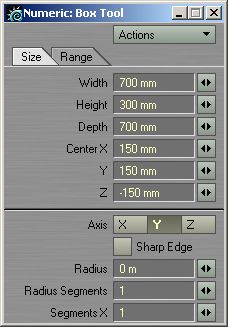
Modeling that joystick top part will go like this ­ click «create» BOX and activate numeric tool. Set size of box to 37cm on X and Y axis, depth 0m, center X 0m, center Y -1,25m center Z 1,46m. Also notice tha ti set 2 radius segments and 2 X segments. This will give us nice round BOX shape after hiting TAB key to tunr on SubDs (SubPatches/metaNURBS) mode. After hiting TAB key just «freeze» object (ctrl+d) and make same thing as before wiht buttons and other parts. If you forgot what you need to make here is reminder (last one ). When you freez object you have lot of polygons, select them all (wiht laso) and merge polygons (shift+z). Then you will have only one polygon but many unneded points in middle. Select thos e»o point polyfons» in point statistic window (just click on «+» sign on left side) and delete all 0 point polys. Then you will ahe somthing as on my right image.


Next steps ofcourse is «solid drill» with «stencil» option adn extruding that part. Be sure you've added new surface to this part also before you stencil it. As you can see on left image i colored polygons to similar color but new surface name is key wich will give me option to select part with just one click on polygon statistic window. After stencil option you need to smooth shift that are once. Then you smooth shift polygons outvard to desired distance (it's not important to much 'coz we will cut that area later). Also good tick with smooth shift option (instead going to numeric tool) is this: 1. hit smooth shift button but DON'T turn on numeric window, 2. click RMB once (looks like nothing happend but it's happend) , 3. click «move» tool («t» key) and move polygons in one direction (by holding ctrl key). That way you get same results as with extend tool or smooth
shift extending but this way is faster and more precise (sometime smooth shift isn't working better on such curvy surfaces so this is better way). Use «bandsaw» tool to cut bottom connecting area in 3-4 rows and move these points little bit up to simulate smooth conection between those parts a showed on right image. Do that by this way : Select two bottom polys in one direction, then hit «bandsaw» and use cut that part in middle. After cuting (in polygons mode) switch to «points» mode and you'll have points already selected. Move them upwards just little bit and repeat that 2-3 times untill you get nice smooth edge ­ right image.


Now we need to align top of this joystick part. Top end of this is sticking out from phoen level as much as buttons are so follow this steps now. Put phone in first foreground layer and buttons in background layer so that we can see how much they are sticking out. Best visible in top viewport.

Then select all top polygons and merge them (shift+z) into one big polygon as showed on left image. Now just select and delete those 0 point polygons (as many times before trought point statistic window). Then go on buttons layer to see how far buttons are sticking. Do that on this way ­ Select one point on button wich is sticking most ina hit «i» key wich will bring you info window and show you all position values of this point ­ look at right image.


OK now you see all three axis value for this button (x,y,z) and see that we need to copy (or write down on paper) Z value. I use copy option in this way - selecting Z value on info window by LMB outline and ctrl+c
shortcut (windows style works on this info panell). Then open «set value» tool (ctrl+v) and paste (or write if you used good old pen and paper) that value into Z filed as left screengrab image ilustrates. After clicking OK in set value tool you'll get nice and precise aligned edge points and perfectly flat top polygon wich we need for next steps. Then you need to smooth shift (size option only) to polygon few times and round that top edge as we did on bottom connection part. Since top edge is really smooth and rounded on real phone i sugeest same thing as on bottom part with bandsawing and moving row of polygons by tiny amounts but this time to bottom (donw towards phone object). After you get similar shape like i did (showed on right screengrab image) just color/resurface that middle flat polygon to something like «glass for battery led» 'coz this is made of glass (transparent plastic actualy) on real phone. That's because inside (behind transparent plastic) of this is hole where you can see tiny little LED wich signalise (red color blinking) you when phone battery is empty and it's time for recharge ­ really nice trick by Sony Ericsson . So if you want to make close shot renders just put inside of that one small ball object to simulate LED object or make this transparent plastic very dark and just semi transparent.


It's time for modeling more buttons on front side. Make BOX object wiht 3* X and Y segments in new layer and move points to get similar shape as i did. This is general shape of button but on low poly before we hit freeze ­ left image. Then bandsaw and cut that shape like right image shows. Then try to hit TAB key to see how nice button shape acctualy is ­ that's just checking is shape right so go back in non subDs mode (hit TAB).


Now you need to move these points (left image) litlle bit invard (closer to phone body) to follow right shape of buttons (look at TOP view to see how much is moved). Then move polygons litlle closer to phone body and extrude polygons invard and delete back face of button ­ right image (look at perspective window i already
deleted back side)


Now you will need one small «bandsaw» on extruded area to keep edge enough sharp in SubDs mode (i used 0,95 or 0,05 depends did you selected polys in cw or ccw order). After you hit TAB key it looks very nice and smooth button as we need ­ middle image. Then just hit Freeze (ctrl+d) button to transfer object into normal polygons as showed on right image. After this just select few rows on extruded part and «banglue» them.


Then just use «mirror» tool to copy button on right side (X axsis) and start «solid drill» with stencil optin to stencil buttons in phone body. Now you should have nice shaped button outline on both sides ­ left image. Next merge top polygons on both sides in to one biger and bevel a litlle bit or smooth shift with only size settings (both tools can do this part) to make small outer ring of polygons ­ right image.


Next to do is beveling edge few times for smooth edge and then smooth shift hoel to make room for buttons ­ left image. After making nice hole you will need to resize buttons 'coz hole is little smaller than buttons now.
So just select one button at time and clcik on «size» button (shift+h). Hold down ctrl key while you drag mouse and you'll see how button is resized exualy on all sides. Just resize by eye untill it fits in hole and move to position like right image shows. Repet that process for other button also or even easyer delete that other side button and hit «mirror» tool to mirror this one wich you already resized and placed on other side automaticaly.


Now copy those buttons into new layer and rotate buttons upside down and set to position for drilling like left image shows. Then smoothshift just in size to get nice outer edge polygons. If you get overlaping corners while you smoothshift or bevel (middle image) you will need to move points manualy before extending cenet polygon in deph. Right image shows how it should look after moving points in place manualy.


Then go for usual smooth shifting and beveling to make hole wiht smooth edges as we did on uper buttons ­ left image. On right image you can see buttons in position. I used same technique as before, small resize and moving to position and then mirror other button.


Next step is to separate phone body. Front panel is made from two pieces like you can see on resource images (uper black blastic and lower aluminium). So now i'am starting to cut that parts. This part is hard to show in pictures but i'll do my best. Look very close at resource image and you'll see that lower part follow buttons shape and it goes completly trough side gaps what we made earlyer . Now stencil that shape into front of phone to psihicaly separate those parts. So try to make shape i showed on left image and set to same position on left or right side and then wiht mirror tool just make other side. That shape is need to be extruded to depth but not more than side gaps 'coz we will connect it with that side gap later. After sucessfuly stencil you should have look as i did on right image. Then you need manualy to weld some points on corners of this stenciled shape.


Next is process of making anoter stencil under that joystick area. Copy polygons form joystick round edge and move, extrude them (left). After that stecil (middle), then weld points at corners and select outer edge polygons of lower buttons and give all that common surface «side gaps» what we used before (right image).


Now it comes tricky part Select all «side gaps» surface from polygon statistic window and then deselect all polygons already inseted (leave only that new part we aded recently). Then just click «smooth shift» and put value -7mm wich will inset this new set of polygons and give us this nice gap between surfaces (left image). As you can see on right image now i have complete front and side of this nice phone. And it realy looks good and damn close to real thing so now i'am moving modeling part to back side and bottom of phone. It's
good time to look cliser at first page where i showed resource images. As you can see there is plenty of details on that back pannel and it need's good look before starting. It has camera, SE logo, soem insets and one metal rounded part wich is actualy made form rubber in my phone (i don't have clue why on resourc eimage tha tis made in metal). That part is acctualy cover for hole where you stick belt clip. Also notice there is exactly 11 equaly shaped insets on battery cover (i counted them) wich need to be inseted into back of phone.


It's time to findout why i aded those gaps and what's usege of them . Select all «side gaps» polygons trough polygons statistic window and hit «x» key to cut and «v» key to paste them into new layer. This is very cool since now we have all parts of phone separated and we are able to select parts by «select connected» in display panel (shortcut is «]» key). Look at left image how i isolated gaps into new layer (background layer in this case). Here is way how will this benefit our workflow from now. Select any polygon on back of phone and click «select connected» in display tab, then cut/paste back side of phone into new layer and you'll get what i have on right image. Why i did that ? Simply now i can very easy control next steps wich is solid drilling back part of phone and i don't need to wory about front part or that i will accidently mess anything already finshed. I could use «hinde unselected» tool in display tab but then i wount be able to put front part into background layer while i work. But if you prefer that way feel free to improvize .


Now make one box object for stenciling back part area. This is acttualy part where phone opens for removing battery so put this at side lower button (at his center) like i did on left image. Odcourse this needs to be stenciled 'coz that's part where battery cover is separated form rest of phone. So do stencil and smoothshift about ­1,2cm and after that cut/paste that gaps area into layer where is rest of gaps ­ right image.


Starting to model that 11 insets i mentioned earlyer. Make one thin box object in new layer and set position just few cm above that gap we made on batery cover. Then click «clone» key and put values as i did on left image. That will give you (after clicking OK) total of 11 equal parts ready for stencil (left image). Asy ou can see i aded new surface to that part 'coz this isn't gap it's just inset for easyer grip when you try to open baterry cover. Then select all stenciled area and use smooth shift to inset that griping area ­ really easy like on right image.


Slect this bottom part wich is left after smooth shifting. We don't need that part 'coz there is our side gaps area so just select that 22 polygons and delete them (selection showed on left image). Then you'l lneed to select uper side of every inset and do small smooth shift to make edges looking smoother ­ middle image). After a vhile you should have nice rounded edges. I did two smoothshift for every side (right) but one will be good also .


Modeling SE-logo hole. Create 50-60 segments extruded circle and set into position like on left image. After stencilin that into phone just merge two polygons and bevel few times to ger very rounded edge and deep hole for fiting SE logo wich we will make later ­ right image.


Now copy one row of points (near top) and make new polygon in new layer. After that just Bevel few times to up for making that SE-logo fit in hole as on left image. Now we need to solve that top polygn and turn him into many separate ones. DO that by selecting top polygon only (like on left image) and click «spikey» tool on «multiply» tab. Then click on selecte polygon in perspective window. That will turn top polygon in many trinagles wich will fit polyflow of botom polys and make nice round ball top when you turn on smoothig (later)­ look at right image.


Now rescale that ball with «scale» tool and make just small resize like 99,9%. That's bacuse we don't want points on same place and now i'll extend bottom part of SE logo. Select botom row of polys and click «extender» under multiply tab (it'll apear liek onoth happedn but it is), then just use «scale» tool again and
strech points/polys to inside of hole and use spikey again ­ left image. After that just round that top edge to make it smother (use bandsaw to make few cuts and move points around edge) ­ right image.


Making hole for camera goes on usual way with solid drilling into back cover ­ make 60-70 segements extended circle (left image). After drilling smooth shift polygons and merge top part into one polygon at bottom like right image shows. Also don't forget to delete «0 point» polygons after merging center polygons into one.


Next i'am explainign how to make camera hole, i used that rounded circel with what i drilled back cover hole. Usual things like smooth shifting an dbeveling polygons will give you something what looks like camera box like left image shows. Now we just need top glas and camera lense inside this.

That's easy just coppy bottom polygon and smooth shift/bevel few times to get similar shape as on my right image. Then just place one rounded polygon wihc will be glass over top of camera lenses.


Now you have camer aim position and glass over top of lenses (i made that glass polygon emi transparent and light green color ,but you have «side gap » surface/polygon going trough camera – lefti mage.Just witch to layer where you pasted gap and use knife tool to cut and delete them in area wich is overlaping camera.Like i did on my right screengrab.


Next is driling that ribber/chrome hole on right side of camera. Process is always same so i won't repaet myself again. Right side image shows steniceld and smooth shifted hole. I aslo added extra smooth to edges but it's not necesary for this par. I just like to complicate things with that micro beveling stuff .


Addin that rubber/chrome (it's rubber on my phone but chromed on resource images) part in hole is easy ­ just use that polygons what you used for solid drill/stencil to make this hole. Resize it to be smaller and smooth shift few times untill you get similar results like my left imege shows.

On right image you can see preparations for drilling one triangled shape into back cover just under camera hole. That's just inseted sign wich shows where to pull if you want to take of battery cover.


After solid drill / stencil procedure i just selected that tringle material and smooth shift (only size option) once to have not so sharp edge but not too smooth either ­ left image. And now you have nice cool and finsihed back side of phone like I do on right screengrab .


Making battery charger connector. First step is to select, cut/paste side of phone into new layer. Then just make boxy object under phone. One edge is little bit rounded so look at top view of left screengrab how round i made it. It's just extended box in right position with two points aded in corner and moved to make it rounded (you add points on object by selecting object in spline mode and then click «add point» tool, but
remember to do that before extruding BOX. After solid drill/stencil tool just smooth shift polygons few times but try too smoothout edge 1-2 times so it won't be sharp on render. This is just hole for charger connector wich will be fitted her elater ­ look at right image to see.


Next thing is drilling hole for external heaphones (i think this is for bluetooth clip or so but i'am not sure 'coz hole looks like there is nothing inside maybe is just cliping hole for connector - dunno). It's not too important what's for but since it's there so it need to be modeled properly . Make this shape near that charger inset (i don't know how they placed this hole 'cot it's not alingent wiht anything around, maybe it's needed distance form charger so dont wory about exact place) on left side (buttons facing up) of phone ­ left image. OK now i stenciled that hole and made few (a lot of them acctualy) bevels to inset hole properly. No need for such drastic number of bevels beacuse this hole is really tiny one on whole object but i'am loving ultra realism so i wan't to be able to get camera so close that you can see every single edge and inside of hole if needed. It's up to you will you inset hole with 2-3 bevels or make it like i did with plenty of them ­ right image. Ok now when that hoel is finsihed you wonder how do i know that this is realy something for headphones ? Heheh that's easy ­ in next page you'll see that above this hole there is sign wich shows headphones shape so it wasn't just a lucky guess .


Here is my phone sign process. I can't show you every single step (that would be too big tutorial) but basicaly i made this headphone shape from one ball (make ball, select one row of polygons and delete unselected ones. Then just move all points to same X value with «set value» tool wich will make it look one dimensional). Then making lower part (what is put on ears) is easy. Just click «+» key and click with RMB to put points on place. After puting basic shape points just select 4 by 4 and make polygon by «p» key, then just copy and paste other ear part to oposite side with mirror tool. After that i just used Knife tool to cut edges 'coz we will make this headphones in SubDs mode so they need to be nicely shaped after hiting TAB key). On left image you can see position and look of headphones sign. It need's to be positioned little left from previous hole so don't center it. Next step is tunring on SubDs wiht TAB key and freeze object for stencil tool. After freeze merge polygons with merge tool (shift+z) ­ right image.


Extrude phones logo model as usual and then use solid drill / stencil that headphoen logo into phone body. Then merge polygons and bevel once as left image shows (just remember to delete «o point» polygons after merging polygons 'coz some of them will sure left unneded. Next step is to inset (smooth shift tool) this sign into phone body. I used 1,5cm inset deeph wiht smooth shift so just use that. Then you need to bevel edges
beacuse this headphone inset is very very rounded on edges (interior and exterior). This will be tricky step and if you use too big steps points in edges will probably overlap each other and you'll have wierd polygons caused by that effect. Only way to solve this in LightWave out of Box (without using some other external plugins or tools) is to move overlaping points manuly one by one. Its tedious job but this is needed for good rendering so try to beavel edges at least 2 times if you dont' have patience to do it 4 times as i did . Try to insed inner side with same values as you used on exterior edge and you will have very rounded edges when you turn on smoothing in surface editor. Also take note that you won't be able to bevel all three parts together. You'll need to bevle each one separately to keep them centered , otherwise beveled polygon won't be on center and will look bad like you used some offset and we don't want that.


Left image showes how i made «charger logo» on right side (buttons up) of phone. This is non SubDs mode (before TAB key and freeze) so that you can see how it should look. It's very simple model and i will now turn that into subDs and frezze just like i did with right side headphones logo. After you extend polygon just make usal solid drill stencil wiht smoothshifting and beveling edges ­ basicaly same process as we did last time with heaphones logo ­ right image shows final results..


Last hole on this phone i promise . Under charger connector there is one wierdly shaped hole. Look closely on left image and try to mimic that shape i made. It's made fwitm manual placing points and then knifing polygons to preserve rounded top part and straight bottom when i hit TAB key to have subDs before freezing. Right image shows this wierd hole in place . How to explain proces sof makin that ? Hmm just usual bevel and smooth shifting untill you are happy with shape. It just need one small part inside.


Make bottom polygons of this hole ­ left image and then make one BOX polygon iside this hole as right image shows and bevel (or smooth shift) front edhe once so it won't bee too sharp.


Making battery charger goes this way. We need one BOX object in that hole made much earlyer. I copyed polygons form inside of hole and made front part flat (set value key on points). Then i resized box to be just little bit smaller than hole (i used 99.9% on size) but still very tight. Then next step was to recreate front polygons manualy, after that i just adjusted edges to be little rounder and results you can see on left image. No we need to create 5 holes in this and 11 golden conncetior insted betwen holes. On right screengrab you can see driling parts in position and read for action. Those Biger ones are holes and those smaller are small holes with gold contacts inside but all of them need to be inseted first after stencil option and they have square edges wich need to be made also. Process is same just extrude polys first nad then solid drill them.


First merge inseted polygons in one so tha toyu can use bevel tool properly then bevel edges of all holes first and use just small amount like 3-5mm. After that inset plygons about 3mm to get similar edge as i did. Next step is inseting (with smooth shift) biger holes (5 of them) deep inside and inset smaller ones (all equaly sized) just about 1cm or so 'coz that are golden connectors wich need to be in reach for connecting charger properly. Good thing now it would be to colorize charger connectors separately (give them different surface name) so that you can select them later. I give them surface name like «battery charger connectors ­ gold» so that i easy recognize that in surface editor ­ right image.


Just one more thing before i can say this model is finsihed. We need to model LCD under front screen so that he can be maped with nice backgorund images and be really under the screen glass. Select screen polygons in «surface editor» and make them semi transparent by adding Lightwave native glass preset with IOR (index of refraction) 1.0 wich is under «general» presets called «Glass_Inside». I nthat way you will see trough screen plastic and will be able to adjust poygons in position.
Here you can see how i set LCD screen polygons under this previously made plastic cover on screen.You dont' need to model this but it wil add to realism 'coz LCD is flat you will easy map one image on that later when you surface this nice model. As you can see on right image this model (and tutorial) is finsihed. Since i'am not covering texturing here you can go to sonyericsson web pages and downlaod images, logo and screen maps to map them in position before you render .


Now it would be very good time to check for some point and polygon statistic. Select all layers (by holding shift key and LMB clicking) and look under point statistic window to see is there any «0 polygons». If you have then just select them by that «+» sign and delete. Then do same thing for polygon statistic window ­ open polygon statistic (while you are in polygon selecting mode just hit «w» to bring up statistic window) and look do you have any number under «2 Vertices» and delete them if you do have any number there. After that you can be pretty sure you have properly built model wich will be good looking on render (otherwise you could have some rendering errors if you have those 0 point polys and 2 vertices polygons). Now go and texture this nice 3d model of Mobile-phone .


Here it is ­ SonyEricsson T610 3D model
 

About

Site Info

Text

best tutorial for all Copyright © 2009 Community is Designed by Bie