Box Tool
Pen Tool
Lathe Tool
Flipping Polygons
Assigning Surfaces
Basic Subpatches
Using Layers
Glass Materials
Reflective Materials
Basic Camera Settings
Basic Light Settings
Basic Rendering Options
Picture 15 shows the final render:

Picture 15: The final Glass Bowl Picture (Click to enlarge)
The Bowl Shape
We are going to use the Pen Tool to create an outer shape of the bowl, but before we do this, we need to adjust the Modeler. In the Bottom Left Viewport, change the View to "Back (XY)" if it isn't already, then place your mouse pointer in the centre of all four views and drag it up to the right. This will increase the size of the "Back" view and we will have more control over what we do. Use the Pan tool in the Back Viewport and drag until the centre of the universe is at the bottom left, look at Picture 16 and you'll know what I mean.

Picture 16: Prepare the Modeler (Click to enlarge)
Now how do you set the grid size to 10mm then? Well, it's quite simple. When you use the "Zoom" Tool, Modeler will automatically adjust the grid size whether you zoom in or out. In the Back View, click the "Zoom" button and drag with your mouse to zoom in. Keep an eye on the Grid Size as you do this, because you'll notice that the Grid Size changes. So zoom in until the grid size says "10mm". Have a look at picture 16 again to see what it should look like.
The Pen Tool
The Pen Tool is quite simple to use. It lets you place points, and as you do it also connects the points with polygons. Like many of the other Tools in Modeler, the Pen Tool comes with a Numeric Panel, which lets you insert exact values on where the points should be created. Activate the Pen Tool now, you'll find it in the "Create" Tab. Once activated, press "n" on your keyboard to bring up the Numeric Panel. As you can see in the Numeric Panel, the default values for all the axis are set to zero, and if you look at the centre of the Universe in the Back View, you should notice that a point has been placed there, like in picture 17.
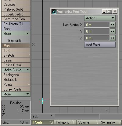
Picture 17: The Numeric Panel for the Pen Tool
The first point has been created, so close down the Numeric Panel now by clicking the "X" at the top right of the Panel, but keep the Pen Tool activated.
We will use the Pen Tool to place points in the shape we want the Bowl to be, and as we place our points, Modeler will connect them with polygons automatically. I used a total of 29 points for my shape, and you can use more or less for your shape if you want to.
Have a look at picture 18; you'll see that I've numbered each point in which order I created them, so try to create a similar shape now.

Picture 18: The Basic Bowl Shape, try to create a similar shape (Click to enlarge)
Deselect the Pen Tool once you're done creating the shape. I created my points in a clockwise order, and this will result in that the polygons will face inwards later on when we lathe it. Does it sound complicated? Lets have a look at the lathe tool and you'll know what I mean.
The Lathe Tool
Now size down the Bottom Left Viewport until all four Viewports are the same size. If you press "a" on your keyboard now, the shape we have created will be fitted nicely in all four Views as well. Picture 19 shows what we have so far.

Picture 19: The basic Glass Bowl shape (Click to enlarge)
Click the "Multiply" Tab and then activate the "Lathe" Tool by clicking on it. We are going to have a look at the Numeric Panel here as well, so press "n" on your keyboard to bring it up. Once the Numeric Panel came up, a real-time preview of the Bowl appeared in the Viewports. As you can see in the Perspective View now, the polygons of the bowl are facing inwards, like I mentioned earlier. We can fix this easily by flipping the polygons later on when we're done lathing. So how does the Lathe Tool work then? Well it's quite simple. It takes the 2D polygon shape we created, and it spins it around 360 degrees, and while it spins it, it creates geometry out of what the 2D polygon shape looks like.
Lets have a closer look at the Numeric Panel then. The amount of sides determines how many times the 2D polygon shape should be duplicated when it spins it. The default value is 24, which will do fine for this bowl. The centre values should all be set to zero, since that's where we started creating the polygon shape.
The Start and End Angle determines where it should start spinning, and where to stop. Picture 20 shows an example of this.
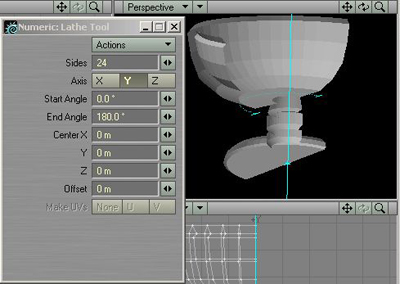
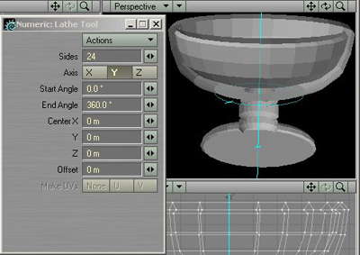
Picture 20: Testing the Angle values
Picture 20 is divided into two. The picture to the left shows a value of 180 degrees entered for the End Angle, making the lathe tool only create half of the Bowl. Using 360 degrees like in the picture to the right will spin it all around making the Bowl complete.
So the final settings for the Lathe Tool should be what picture 21 shows.
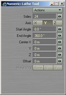
Picture 21: The settings for the Lathe Tool
When you've entered these settings, just close down the Numeric Panel and hit Space to perform the operation, then press "a" to fit the Bowl in the Viewports. When you're done with that, press "f" to flip the polygons and we're done!
Assigning Surfaces
What we want to do now is give this Glass Bowl a material. The final surfacing and the creation of the glass material will be done in Layout later on, and right now all we have to do is assign a name to the Glass Bowl. Press "q" on your keyboard to bring up the "Change Surface" panel. Name this surface "Glass Bowl", set the Specular to 50% and click the "Smoothing" button (to activate it), then just click "OK" to apply the changes.
The Glass Bowl is looking a bit rough at this point, but we will take care of that next.
Subpatches
Lightwave can turn objects into Subpatches, which will smooth the polygons out. Then when the sides of the object are smooth, we freeze the Subpatches and the object gets a new smooth shape permanently. Make sure everything is unselected in Modeler, and then hit "Tab" on your keyboard to turn the object into a Subpatch. Notice how smooth the bowl turned out? It should look something like picture 22 at this moment.

Picture 22: Subpatches activated (Click to enlarge)
Now we want to tell Modeler how much it should smooth the polygons. If you hit "o" on your keyboard an Options Panel will open up. You can set various settings here but at the moment we are only interested in the "Patch Division" setting. We will use a Division of 3 here so enter that number in the "Patch Division" field. This means that each Patch in our mesh will be subdivided 3 times when we freeze it. Click OK to close down the Options Panel, and then hit "ctrl+d" on your keyboard to freeze the Subpatches.
The object is now back in to a polygon mesh.
Now I need to say something about surfaces and how they work in Lightwave. As you might know, light bends when it passes through transparent materials such as glass. At this point, our bowl only has polygons facing outwards, meaning it wont appear as solid glass once we render it, know what I mean? If we were to create an inside of this bowl, then Lightwave would know that the glass is solid and it will know when to start and stop bending the light. We can fix this quite easily, all we need to do is to copy the polygons of the bowl, paste them in a new layer and then flip them so that they're facing inwards. Then we will have an outside and an inside for our bowl.
Make sure everything is unselected and hit "c" on your keyboard to copy this bowl object. Now it's time for us to use the Layers. If you look at the 10 small boxes up to the right, you'll notice that black little dot I was talking about earlier in Layer 1 (the box to the very left). This means that that Layer is taken, and we know it is, by our bowl object. Activate Layer 2 now by simply clicking in the upper part of the box; it should look like picture 23.
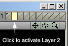
Picture 23: Layer 2 active
Once you click on Layer 2, the bowl object will disappear from the four Viewports. We have a new empty work area for our next procedures, and anything we do in Layer 2 will not affect Layer 1 where the bowl is. Paste the object in by hitting "v" on your keyboard, we now have a second bowl which will become the inside for our main bowl.
Hit "f" on your keyboard now. This will flip all the polygons in our object, making them face inwards instead of outwards. We just need to give this object a new Surface and we are done, so hit "q" on your keyboard again and the "Change Surface" Panel will open up. Name this surface "Glass Solid", set the Diffuse to "80%" and the Specular to "0%". Smoothing should also be turned on. Click OK to apply this surface to the object. Now that the Polygons are flipped and the new surface is attached to the object, it should look something like picture 24 in the Perspective Viewport.
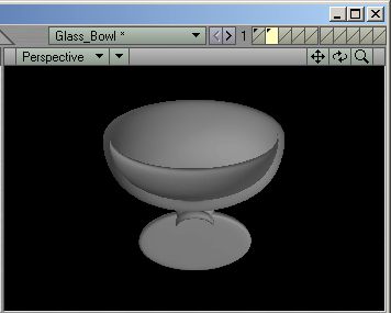
Picture 24: The Flipped polygons with the new surface attached
Hit "x" on your keyboard to cut this object out of Layer 2, then activate Layer 1 again and hit "v" to paste it there. You won't notice any difference since this object will be "inside" the other one, making the Polygons double-sided. All we need to do now is merge the points, since we have a lot of duplicated points lying around. Hit "m" on your keyboard and the "Merge Points" Panel will open up, just select the "Automatic" operation here and click OK. A few thousand points should be eliminated.
Our bowl object is now finished and ready for Layout, but first we should create some environment for it to be in. We're going to keep this very simple; we'll just create a box that will act as a room. Switch to Layer 2 again and activate the Box Tool, then use the values shown in picture 25.
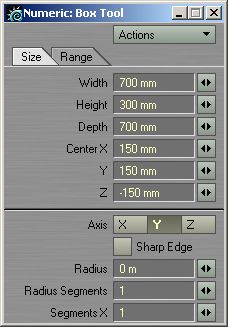
Picture 25: The Box Tool settings
Once you've entered the values, just close down the Numeric Panel. Then hit "Space" to deselect the Box Tool and to create the box. We need to set a new surface for this object, so once again hit "q" on your keyboard, and this time name the surface "Floor". Set the Diffuse to "80%" and the Specular to "10%", then click OK and the new surface is created. We are going to flip the polygons of this box as well, since we want the sides of the box to appear as walls to simulate a simple room; hit "f" to flip the polygons now.
Modeler lets you view two or more layers together at the same time, and now would be a good time to view the two objects to see what they look like. With Layer 2 still active, hold down "Shift" on your keyboard and click on Layer 1. This will make both Layer 1 and 2 active, and the objects in both Layers will become visible. Hit "a" on your keyboard to fit the objects in the view, they should look something like picture 26.

Picture 26: Both objects together (Click to enlarge)
All the objects we need for our scene has now been created. At the upper left of Modeler you should see a "File" button. Click this one and select "Save Object As". When the requester pops up, select a place on your hard drive where you wish to save the object. An advice is to create an "Objects" folder in your "Newtek" folder, where you keep all the objects you create. Name the object "BowlScene.lwo" or something like that.
Since we have 2 layers for this object (the bowl layer and the room layer), Lightwave will save both of them as one object, but it will remember what layers were used and what object was in which layer. I'll get back to this later on when we load the object into Layout.
The Tutorial will now pause for a tour of the Lightwave Layout, but will continue after that one is finished

0 commentaires:
Enregistrer un commentaire