Introduction
In this part we'll be adding more detail on the head and body. We'll be using edge loops (insert edge loop tool) a lot, so hopefully the chapter below will explain those clearly.
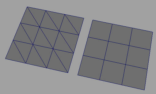
Edge Loops
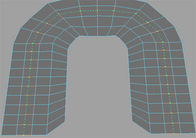
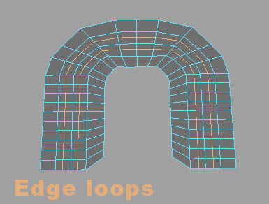
Edge loops are probably the most important thing to a model. When set up right, the model will smooth correctly, and will be easier to model. If you followed the instructions from part one, the model was designed to have good edge loops. I'm going to try and explain edge loops. I'll use train tracks as a comparison.
Like a train, edge loops need ties.
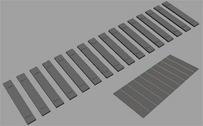
Also like a train, it needs two parallel rails.
Imagine that the edge loop is following the track. As long as the track doesn't break, it could go on forever.
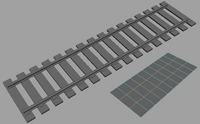
Edge loops can share rails and ties.
Edge loops can only work on quad geometry.
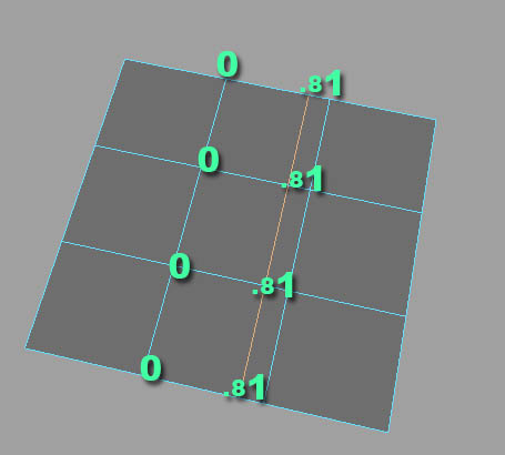
In part one we went into the attributes editor and used the weight attribute to center an edge loop. Weight is from 0 to 1, and is measured from rail one to rail two.
Modeling
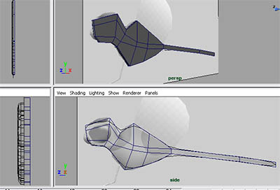
Here's a picture of where we left off.
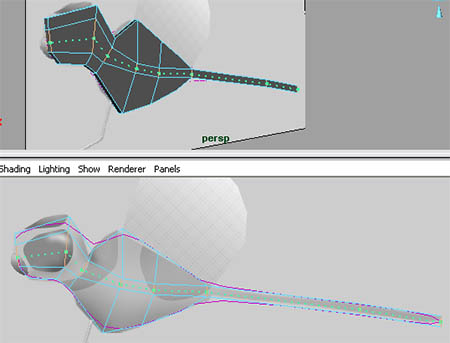
First we're going to need more edges, so we're going to use the "insert edge loop tool" to add them. Go to edit mesh>insert edge loop tool. We need to add one right in the center of the model. So click on one of the edges that's transverse to the edges that we want to follow.
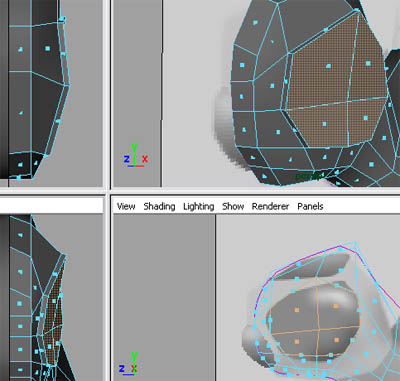
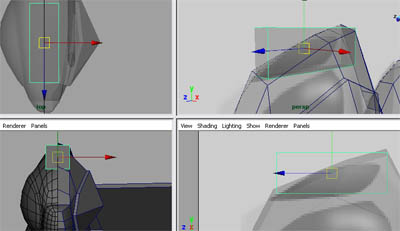
Now go to vertex mode and shape the vertices around the eye.
At the moment, the model's almost completely flat. Use the top and front views to add some width by moving the vertices (notice where the body is widened).
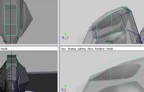
We need another edge loop to round out the underside.
Go to vertex mode and shape the vertices like in the image below.
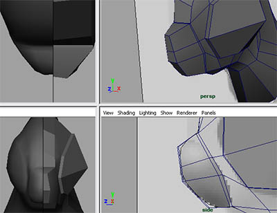
Now we're going back to the eye. We'll add two vertical edge loops and shape it to better match the blueprint.
Go to face mode and select the faces over the eye.
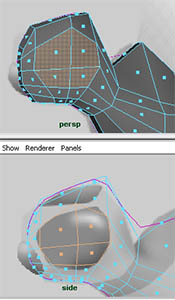
We're going to extrude these faces to form the eye. We'll move it out slightly.
Now select the center vertex in the eye and pull it out.
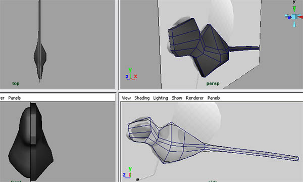
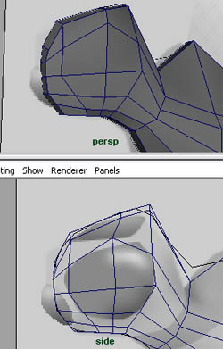
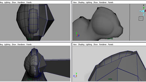
Now I'm going to extrude the nose. First we need to change the base of the nose. Edit the vertices to achieve this.
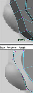
Select the faces on the front of the nose and extrude, just a small bit.

Now, using the same faces, extrude again and go the rest of the way.
Something went wrong here (sort of). If you look at the model from head on you can see that there's a face between the proxy and the low poly. You need to delete this.
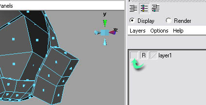
We need to hide the layer. Open the layers editor and click on the V. This will make the layer invisible. Click on the V again to display it later.
Now you can easily select and delete the faces. Also finish shaping the nose.
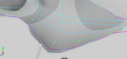
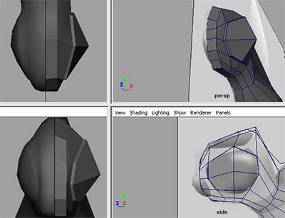
We're going to work on the neck shape now, so add two edge loops and shape them like in the image below.
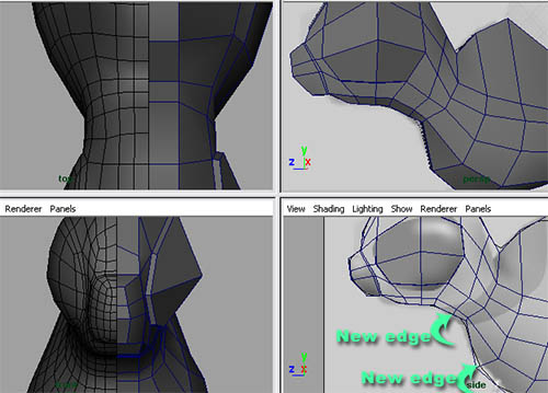
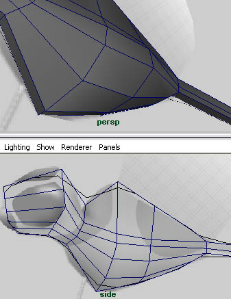
Now for the tail. This dragonfly has somewhat of a spoon tail. First add an edge loop between the two tail edge loops.
Select the vertices on the side and pull them outwards.
Now for modeling the wings. Unlike the dragonfly that used a box to start the geometry, we'll be using a different method of creating geometry. We'll be using the create polygon tool.
First, go to mesh>create polygon tool. Now, from the top view, click to create each vertex of the new polygon to form the wing.
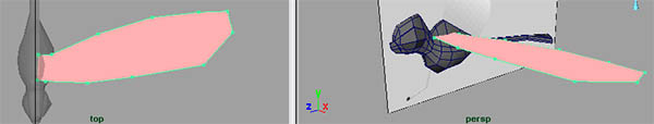
When you're done, press Q. This takes you back to the default select tool. First let me tell you what's wrong with this geometry. It's one big face. Most faces are only supposed to have 3 to 4 vertices and edges. This one has a lot more. Here's how we fix it: we have to convert this geometry into quad geometry. First we have to triangulate it. Select it and go to mesh>triangulate.
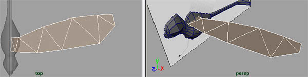
Now, to quadrangulate it, go to mesh>quadrangulate.
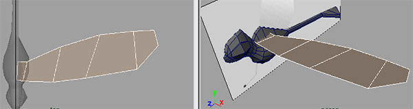
You're probably wondering why we don't go to quadrangulate first and skip triangulating it. This is one of Maya's odd things: if we were to quadrangulate it, nothing would happen. But by triangulating it, the quadrangulate feature can do its job. The reason for this is probably because it's easier to convert geometry to triangles than to quads, and it's also easier to convert triangles to quads. Use the move and rotate tool to position the wing on the body.
We need to add some thickness to the wing. Select the entire object and go to edit mesh>extrude. Move the new extruded faces up a bit.
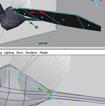
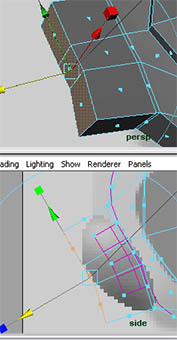
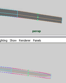
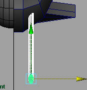
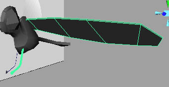
Now for the feet. We're going to extrude the feet from a cylinder along a curve. First we're going to create the curve. We're going to use the CV curve tool.
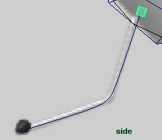
Go to create>CV curve tool. To create CV curve points, click on the view port. Continue this until you've created the curve like the image below. The direction that you create the curve in is important; the curve should be created going outwards.
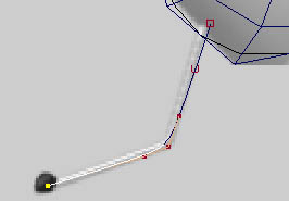
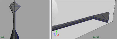
We need to create a cylinder, so go to create>polygonal primitives>cylinder. Now move, rotate, and scale it like in the image below. It has to be in line with the curve.
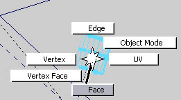
We need to select the faces on the front of the cylinder and the curve at the same time. If we were to hit F11, the entire scene would be in face mode, and curves can't be selected in face mode. This is because they're NURB curves. NURBs don't have faces. So we need to have only our cylinder go into face mode, and the rest of the scene stay in object mode. To do this, right click on your model and select face.
Now select the faces at the end of the cylinder, hold shift on your keyboard, and select the curve.
Now go to edit mesh>extrude.
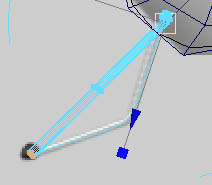
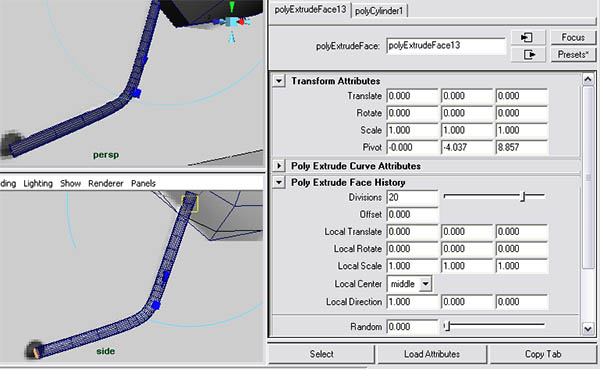
As you can see, there's a problem. It's not completely following the curve. The answer to this is in the extrude tutorial on this website. Link Here's how to fix this.
Select the object and open the attributes editor. Just like edge loops and anything else, we can access extrude settings from past extrudes. Go to the tab polyextrudeface#. Roll down to polyextrudeface history and increase the divisions. 20 to 25 divisions will work.
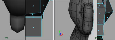
Now for the foot. Create a sphere, move and scale it to the position in the image below. Notice that we squished it a bit horizontally.
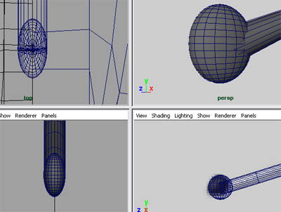
Select the sphere, hold shift, and select the leg and move it like the image below. We'll mirror the other leg later.
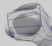
Now for the last piece. This is the little helmet on its head. This will be a separate object because this will be assigned with a blinking, glowing material.
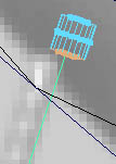
Make a cube. Scale and position it like in the image below.
Add two edge loops and shape it like the image below.
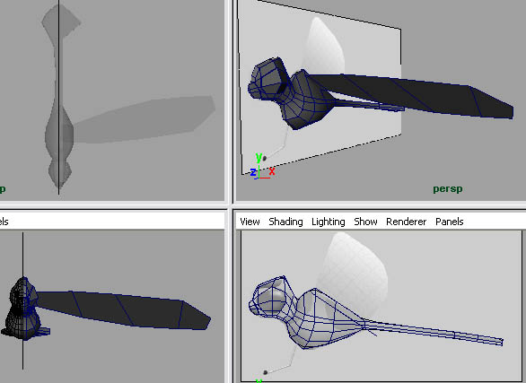
Go to object mode and select it and go to mesh>smooth.
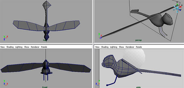
Now that we're done modeling all the components, we're going to mirror the wings and the leg to the opposite side of the model.
First select the wing and the leg all together (use shift). We're going to group them and duplicate the group to the opposite side. To group them, go to edit>group.
Now go to edit>duplicate special... Open the options.
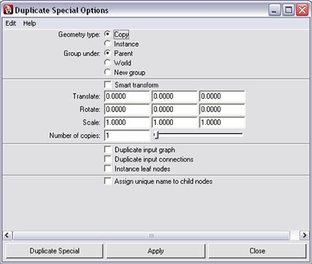
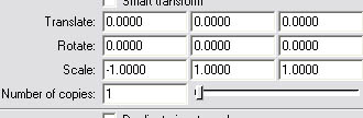
We want to set the first scale option to -1. This will mirror it to the other side. To learn more about duplicate special, read this tutorial.Link
Now click duplicate special.

0 commentaires:
Enregistrer un commentaire