This tutorial series covers how to model, texture, and render a toy dragonfly. This tutorial is aimed at beginners.
Set-up
Download these blueprints.
Link
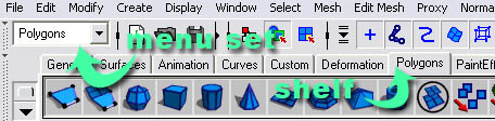
Set the menu set to polygons. Set the shelf to polygons.
Introduction
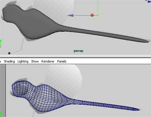
We'll be modeling a dragonfly from polygonal primitives (cubes). This tutorial uses a lot of the extrude tool.
Also, as an additional note, to view your model as a wireframe press 4, to view your model shaded press 5.
The blueprint for the model can be downloaded here:
Link
Setting Up The Camera
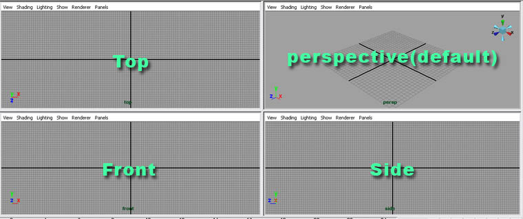
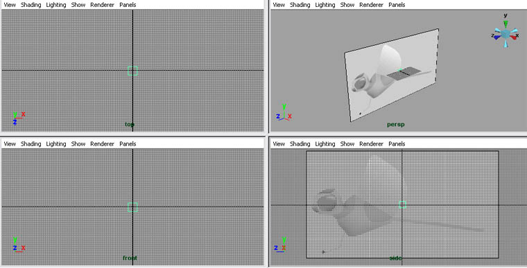
Throughout this tutorial we'll be modeling a 3-dimensional object. Since, when using the default camera you can only see two dimensions at a time, it's best to split the main view port into four views.
To do this...
Go to window>saved layouts>four view.
Setting Up The Image Plane
We'll be using an image plane to display our blueprints in Maya. Image planes are connected to cameras. Example: The side camera's image plane would be connected to the side blueprint file.
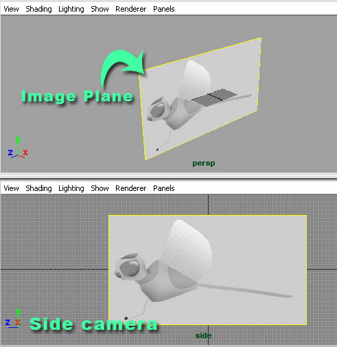
Now let's create the image plane.
Step one - On your side view port, go to view>image plane>import image... Locate the bitmap file that you downloaded as a blueprint on your hard drive.
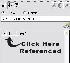
Step two - Now that we have our image plane in Maya, we have to reference it. That means you can't accidentally select it when modeling. Go to display>UI elements>channel box/layer editor.
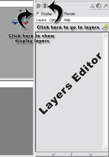
Step three - In the layers editor, go to layer>create empty layer.
Step four - Select the image plane (you may need to click on the green edges).
Step five - Right click on the new layer and go to add selected objects.
Step six - Click the template/reference toggle button two times. When it displays R that means the layer has been referenced.
Modeling
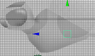
We'll be modeling our toy dragonfly from cubes. To create our first cube, go to create>polygonal primitives>cube.
Use the move tool to move it into the position. Use the image below for reference.
Now press F9 on your keyboard. What this does is put your cube into vertex mode. This way we can select and move vertices instead of the entire object. vertices, edges, faces, UVs, etc. are components. To exit a component mode, press F8.

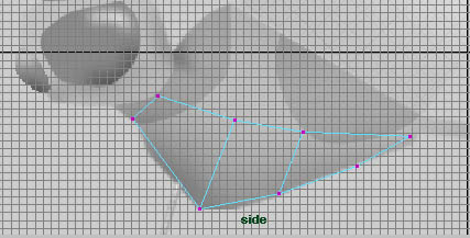
Now you can edit your vertices. Position the vertices, using the move tool like in the image below. Tip - Select the vertices by making a square over them. That way you select and move both sides.
We're going to make an extrusion. To extrude a model, you need to select faces, another type of component like vertices. To enter face mode, press F11.
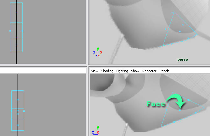
The blue dots in the polygons (squares) are the faces. Every polygon has at least 3 vertices, 1 face, and 3 edges.
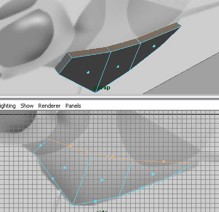
Select the faces on the front of the cube.
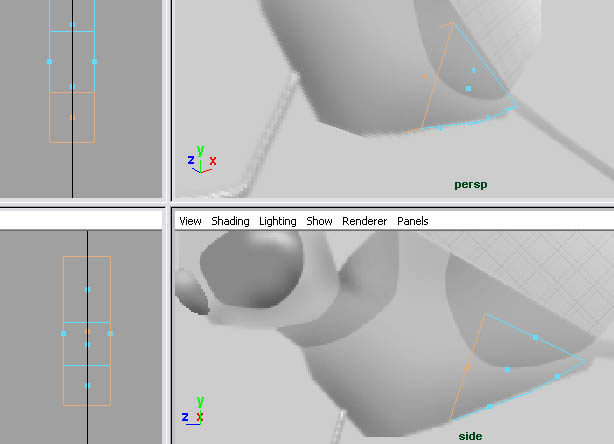
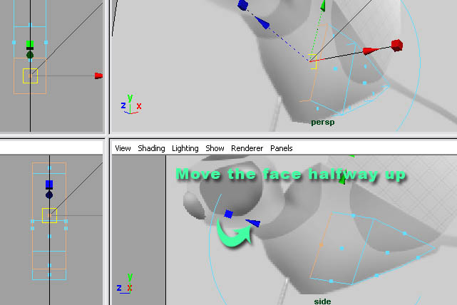
Go to edit mesh>extrude. Use the extrude tool's blue handle to move the faces about halfway up the model.
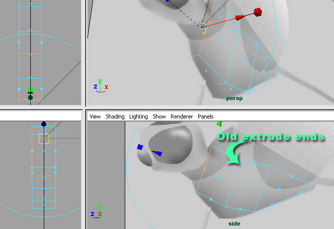
Now we need to make another extrusion. Once again select the faces on the front and go to edit mesh>extrude, and move them to the base of the neck.
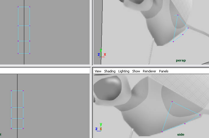
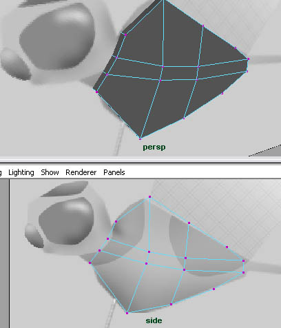
Go back to vertex mode (F9) and move your vertices like in the image below.
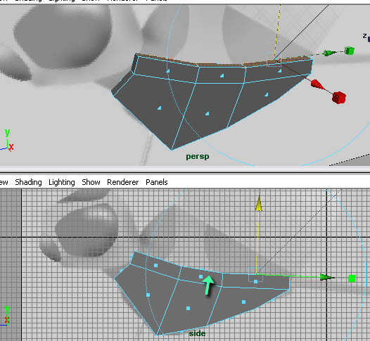
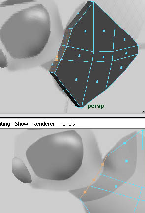
Go to face mode (F11) and select all the faces on the top of the model. I went to shaded display mode so it would be easier to see.
Make another extrusion.
Select the faces that you just extruded and extrude them again.
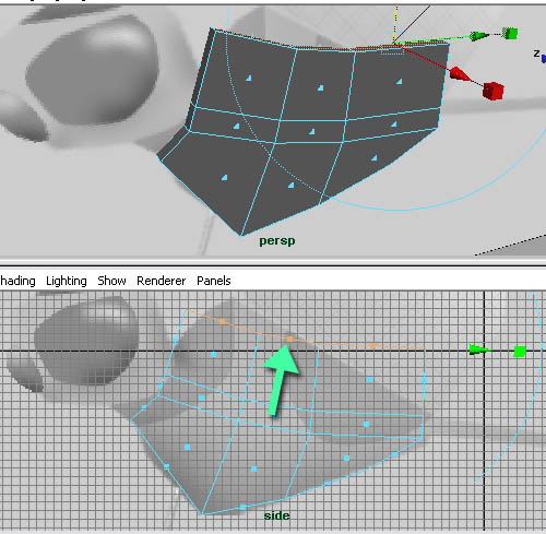
Now go to vertex mode and position the vertices.
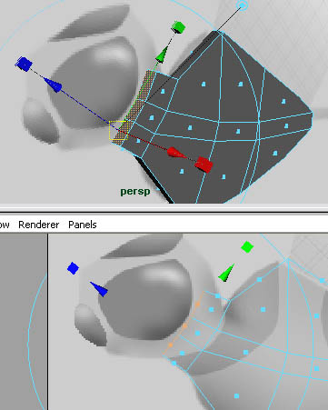
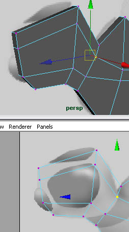
Now that we've got the basic body shape, we need to extrude the head. Go to face mode. Select the faces on the base of the neck.
Extrude them up to the back of the head.
Now make another extrusion to the nose.
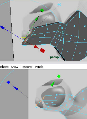
Go to vertex mode and position the vertices.
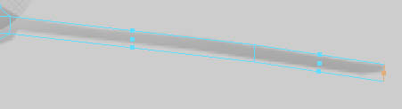
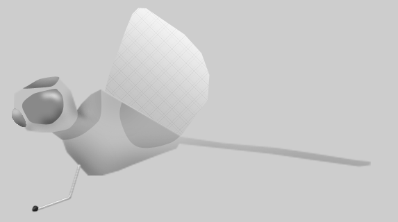
Go back to face mode and select the face on the base of the tail.
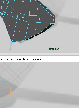
Extrude the face to about 3/4 of the way down the tail.
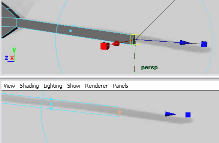
Using the same face, make another extrusion for the rest of the way.
Creating A Smooth Proxy
Most of the time, models will be smoothed when they're finished. Smoothing adds more edges and faces, also smooths out the geometry. To smooth your model, go back to object mode (F8), select the object and go to mesh>smooth.
Now that we have more vertices and faces, it will make the model harder to edit. Also a downside, it's hard to make sure the opposite side of the model looks the same as the side you're modeling. This is where the smooth proxy comes in. A smooth proxy lets you have one side low poly (unsmoothed geometry) and the other side smoothed. The smoothed side will mirror everything you do on the low poly side. So let's set one up. Undo smoothing your model (edit>undo or ctrl+z).
Step one - Select your model.
Step two - We're going to need to cut our model in half, but we don't have an edge to cut it on. We're going to use the insert edge loop tool (we'll be using this a lot more in part two ) to add an edge loop all around the model. Then we'll delete the faces on one side of the model.
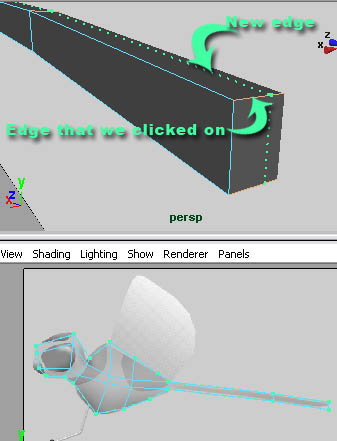
To access the insert edge loop tool, go to edit mesh>insert edge loop tool. Click on a horizontal edge; it doesn't matter which one, as long as it's along the edge that we need to cut.
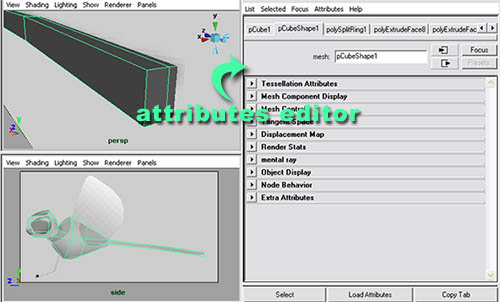
Step three - As you can see, the edge isn't 100% cutting the model in half. We need to have this accurate or the smooth proxy won't work. So select the object in object mode and go to window>attributes editor.
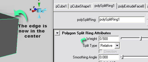
Step four - As you can see, there are a lot of tabs in the attributes editor. The first two tabs are the transform node and the shape node. These nodes, when connected together, make up your model. The transform node contains the information like where your model is in the scene, and the shape node would have information like how many vertices are on the model, where are these vertices ; also it would have face, UV, edge etc. information as well. The nodes behind those two nodes are called history nodes. These nodes are all of your past tools that you've been using on your model. In other words, you can click on any of the tabs and edit any of your past tools you used to edit your model. Now, what we need to edit is the insert edge loop tool. But the history node it creates is called polySplitRing#. Click on that tab.
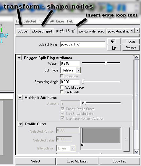
Step five - Look at the weight attribute for the split ring attributes. This is the percentage that the edge loop will be created on the edge. Ours is a bit off; we need to be exactly 50%. So change the value to .5.
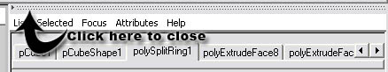
Now that we're done, we can close the attribute editor by clicking on the dotted lines on top of it.
Step six - Go to face mode and select all the faces on the back side.
Step seven - Delete them by pressing delete on your keyboard.
Step eight - Go to object mode, select the object, and go to proxy>subdiv proxy... Click on the box to open the options.
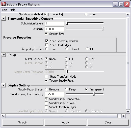
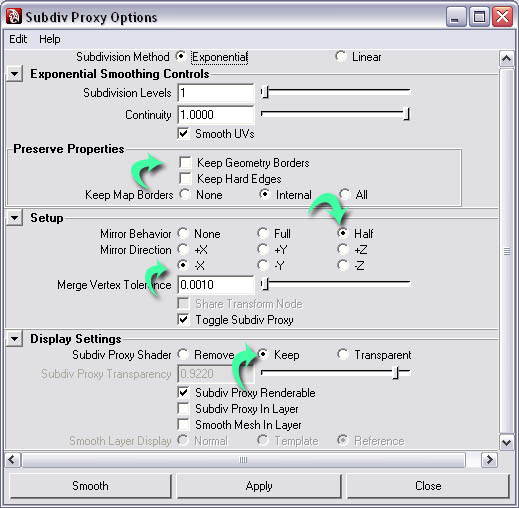
Step nine - We need to set some attributes. First, you want to uncheck keep geometry borders. This will cause the smooth proxy to smooth incorrectly. Second, set the mirror behavior to half and set the mirror direction to -X. The -X axis is the side view, so we want to mirror the proxy on the opposite side (-X). Third, set the subdiv proxy shader to keep. That means the low poly side will remain gray.
Now click smooth.
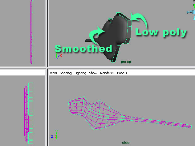
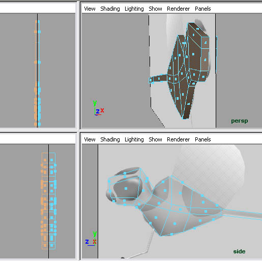
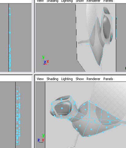
Select the low poly side and try moving a vertex. The smooth proxy side will mimic and smooth the results. Remember to undo. Also notice how the proxy side turns purple when you select the low poly side. That's telling you that these two objects are connected.
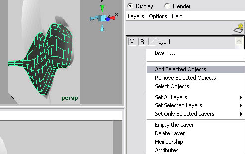
Now we want to restrict our smooth proxy so we can't accidentally select it like our image plane. So select your smooth proxy side, open the layers editor (display>UI elements>channel box/layer editor). Right click on the same layer as the image plane and select add selected objects.

0 commentaires:
Enregistrer un commentaire