Welcome to the Lightwave 7.5 Beginners Guide! This Guide is only an update from my Lightwave 6.5 Beginners Guide to suit Lightwave 7.5; the content is pretty much the same, however, a few new additions has been made in the Tutorial section. We will start out with an introduction to 3D in general, and if you feel that you know the basic concepts already, you can simply skip this part and dive directly into the Lightwave Parts. The best way to get to know the Interface and how tools work is to use them, and tutorials are great for this purpose, so we will be doing a tutorial as I explain the bits and pieces of Lightwave.
An Introduction to 3D
I'd say that the most important thing you need when you want to create 3D art is your imagination, a picture in your head of how you want it to turn out. Your choice of 3D software doesn't really matter, since it always comes out to the artist and how creative one can be. All 3D programs are based on the same idea, where you build up your scenes with Objects, and Objects are built up by Points and Polygons. Take a look at the two pictures below, it's just a box right? Well this is an object, a very simple one, but still an object.
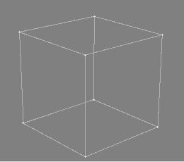
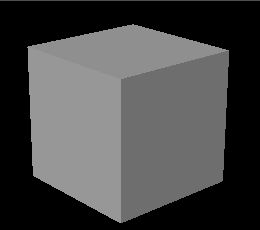
As you can see in Picture 1, there's a point in each corner of the box. Picture 2 on the other hand shows the Polygons, and these are the ones you give materials to, and they are the ones you will see in the final render. I guess you already knew that 3D stands for 3Dimensional, and this is what you work with in any 3D program out there. In Lightwave, these Dimensions are called X, Y and Z, and these could be described as Left/Right, Up/Down and Near/Far respectively.
What's the advantage of using a 3D program then? Well, you can create nice artwork by drawing them in a 2D program, but when it comes to animating what you've created it becomes a bit harder, and this is where the 3D program has an advantage. Another thing to mention is that you can change anything in the pictures you create. If you didn't like the material on a certain object, or if the light setting was wrong, just change it and re-render.
That'll do for an introduction; lets get going with Lightwave!
The Basics of Lightwave
Follow the installation instructions and install Lightwave on your harddrive. Lightwave comes as two separate programs, Lightwave Layout and Lightwave Modeler, and from now on they will just be referred to as Layout and Modeler.
Lightwave Layout
If you start Layout up it should look something like picture 3.
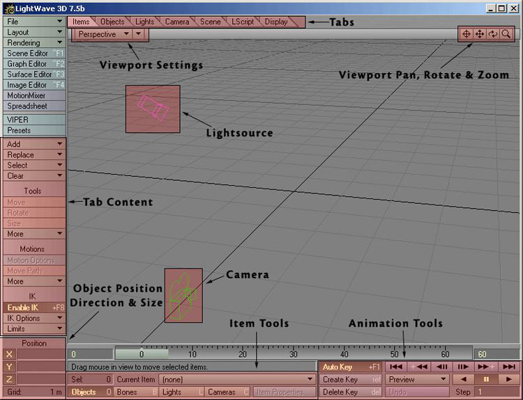
Picture 3: Lightwave Layout (Click to enlarge)
This is where you load objects you've created, give them textures, edit lights & cameras, animate things and render your final pictures. As you can see I have added a few descriptions on some of the items in picture 3. However, we will not start the tour in Layout, but we will get back to it later on in the Guide.
Lightwave Modeler
If you load Modeler up, it should look something like picture 4.

Picture 4: Lightwave Modeler (Click to enlarge)
The Modeler lets you model all the necessary objects you need for your scene. You also prepare your objects for Layout here, like attaching surfaces to them etc. I put a few descriptions on picture 4 as well, and we will get to know the interface better next.
Getting to know Modeler
We'll start with a few explanations on how Lightwave is built up, and then we'll start the main tutorial and learn the tools we use as we go along.
The Interface & Workflow
The Workflow is one of Lightwave's stronger areas. If you look at the Interface, you'll see that every Tool or Button is named with text. No image buttons that takes ages to learn, plus that the interface is very clean. You also have shortcuts on your keyboard for almost every Tool in Lightwave. The menus are also configurable and you can create your own menus to fit your own needs.
Keyboard Shortcuts
If you look at the "Box" Tool button in the "Create" Tab, you'll see that in the right side of the button there's an "X". This means that a capital X is the shortcut key for the Box Tool, so if you hit "shift+X" on your keyboard, you'll see that the Box Tool gets activated. This is how it works with all the other Tools that have a key assigned to them as well.
If you would like to assign a shortcut to a Tool that perhaps doesn't have one, hit "alt+F9" on your keyboard and you will get a list over all the Tools available, and a list over all the keys on your keyboard. You can also access certain setting panels from the "Modeler" pull-down menu at the top left of Modeler.
Plugins
Lightwave comes with lots of Plugins that you need to get things working properly. We will start by installing these in Modeler. At the top left of the Modeler window, you should see a button named "Modeler". If you click this one with your Left Mouse Button, you will get a small menu with a few sections and options. One of the sections is named "Plug-ins", so click that one and a sub-menu will appear. From this sub-menu, select "Edit Plug-ins".
A Panel will appear and this is where you control your Plugins. If you didn't install your Plugins already, we will do it now. Click the "Scan Directory" button on the right of this Panel, and a browser window will appear. Browse to your Lightwave Directory (on your harddrive) and find the Folder named "Plugins", simply just mark this Folder and click OK. Lightwave will now install all the Plugins it will find automatically. When it's done you can simply close down the Plug-ins Panel.
Display Options
Modeler has got four Viewports by default. Each of these Viewports can have their own unique settings. Open up the Display Options panel by hitting "d" on your keyboard, it should look something like picture 5.
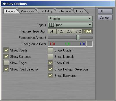
Picture 5: Display Options Panel
The first tab called "Layout" in this panel contains a few global settings. This means that if you change something here it will take place in all of the Viewports. As you can see I've turned off a few options here, and this is just my own preference. What we will change though, is the Top Right Viewport (Perspective View) and how that one should appear. So to edit just one of the Viewports, click the "Viewports" Tab. The first thing to do here is choose which of the Viewports we want to edit, so click on the "TR" (Top Right) button to select that one, then use the options that picture 6 are showing.
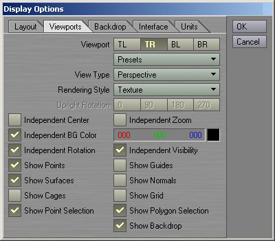
Picture 6: The settings for the Top Right Viewport
Once you've entered all the settings here, just click OK to save it, and if you look at the perspective view now, it should look something like picture 7.
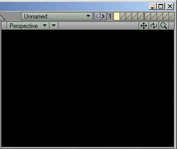
Picture 7: The Top Right View/The Perspective View
There are a few more things we are going to change in the Display Options Panel, so hit "d" once more to bring it up again. Click the last Tab - "Units", then use the settings shown in picture 8.
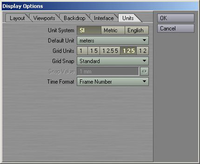
Picture 8: The Units settings
Once you're done with these settings, click OK again to save the changes.
Each Viewport has got a Pan, Rotate and Zoom Tool, and a variety of render modes, picture 9 shows the Toolbar for one of the Viewports.
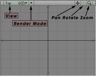
Picture 9: Viewport Tools
As you can see on picture 9, this view is set to "Top XZ", but you can easily change it to any of the others by using this pull-down menu. Just to the right of the View menu you can select what type of Render Mode you wish to use for that view, such as Wireframe, Smooth Shaded and so on. The Pan Tool lets you Pan the Viewport, and if you prefer to use the mouse and keyboard, just hold down the "Alt" key while you click inside the view with your Left Mouse Button and drag it around. The Rotate Tool only works in the Perspective View. In any Perspective view you have, you can also hold down the "Alt" key while dragging in the view, which will work as a Rotate Tool. The Zoom Tool will zoom in or out using the centre of the view as a target.
Modes & Tools
At the bottom of Modeler, you should see two buttons named "Points" and "Polygons". These are the two modes of Modeler, and will give you more control over what you are doing when you model your objects. If you read the first part of this Guide then you should know what Points & Polygons are, otherwise, move back and read it. It is essential that you know what Points and Polygons are if you want to get anywhere with modelling.
The Tools that come with Modeler, has been nicely categorised under the Tabs, just above the Top Left Viewport. The "Create" Tab is open by default when you load Modeler, and if you click any of the other ones, you should see that the Tools to the left of Modeler changes. To activate a Tool, simply click on it once. Activate the Box Tool in the "Create" Tab now. If you move your mouse over any of the Viewports now you can see that the mouse pointer has turned in to a small 3D box. The same thing happens with the other Primitive Object Tools, the Ball Tool turns into a small ball, the Disc Tool into a small cylinder and so on. To Deactivate a Tool simply click it again or hit "Space" on your keyboard. We are going to go through the most common tools a bit later in this Guide, to get to know them better.
The Numeric Panel
Almost every Tool in Modeler comes with a Numeric Panel. This panel lets you enter exact values of how you want the final result to turn out. For example, using the Numeric Panel when you have the Box Tool activated lets you enter exact values of how big the box should be, and if you're using it when you have the Move Tool activated, you can enter an exact value as to how much you want to move the object and so on.
Activate the Box Tool and hit "n" on your keyboard. Once you hit "n" the Numeric Panel will come up showing you default values of the Tool you selected, in this case the Box Tool. Once you activated the Numeric Panel, a box was created in real-time in the ViewPorts of Modeler, and as you make changes in the Numeric Panel, it will affect the Box in the ViewPorts. Close down the Numeric Panel by clicking "n" once more (or by clicking the "X" at the top right of the Numeric Panel window), and then hit "Space" on your keyboard to deactivate the Box Tool and to create the Box. Don't delete this box; we'll need it later on.
The Hub
The Hub is what Lightwave uses to communicate between the Layout and the Modeler. When you've finished modelling your objects for instance, simply send them to layout via the Hub. This increases the workflow even more, and makes Lightwave more like one program instead of two. As soon as you start Lightwave up, the Hub will automatically start running, you'll notice a small green icon in the System Tray. If you don't have enough ram in your machine, and Lightwave tends to get slow after a whiles usage, then you can turn the Hub off via the System Tray, its requirements are pretty high.
If you would like to run without the Hub permanently, then do the following steps. Add two shortcuts to Layout and Modeler in your Windows hotbar (down where the Start menu is). Right click the Layout shortcut and select Properties. In the Window that comes up, you should have a "Target" string, indicating where on your harddrive the executables are. In the end of this string, add "-0", making it look something like:
...Newtek\Programs\Lightwav.exe -0
Do the same with the Modeler shortcut, and the next time you run either of them, the Hub will not start automatically, saving you lots of RAM.
Objects & Layers
You can have many objects loaded at the same time in Modeler, and just above the Top Right Viewport you should see a pull-down menu where it currently says "Unnamed". This is the object you are working on at the moment, and if you have more than one object loaded in Modeler, you can switch to which one you wish to work with here.
To give you even more control over your objects while you work with them, Modeler brings you Layers. Each object can have 990 layers, and this is more than plenty. Just above the Top Right Viewport you should see 10 small boxes, and these are the layers. Picture 10 shows the Layer Tools.
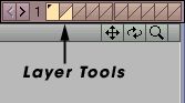
Picture 10: The Layer Tools
The one to the very left is lit up with a yellow colour, which means that it is active. As you can see there's a little black dot in this Layer. Remember the Box we created earlier? Well, the little black dot indicates that this layer has got an object in it.
If you look at picture 11 you will see that each of these boxes is divided in two. The Top part indicates Foreground Layer, and the Bottom part indicates Background Layer.
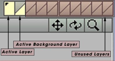
Picture 11: A Closer look on the Layers
One of the new things since LW6.5 are the Layer Groups. Earlier you could only have 10 layers per objects, but with this feature you can have 990. 10 Layers per group and a total of 99 groups. Picture 12 shows the Layer Groups.
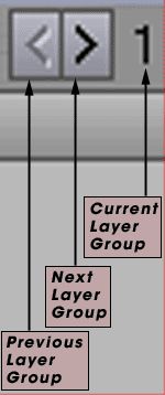
Picture 12: The Layer Groups
Lightwave Universe
Both Modeler and Layout has something called Lightwave Universe, and the Universe has got a centre spot. As you can see in the four views of Modeler, there are two lines in the grid pattern that are a bit thicker than the others. Where these two meet, that's the exact centre. The values for X, Y and Z here are all zero.
Working in the Bottom Left Viewport, put your mouse pointer at the exact centre and watch the Position Window. It should look something like picture 13.
Picture 13: Closer look at the Axes
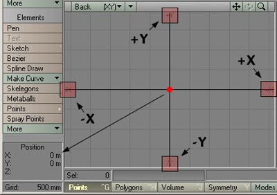
The red dot in the middle of the View indicates the centre of the Universe, and as you can see in the Position window, the values are both zero there. The picture also shows that each axis has got a negative and positive side. In my example I'm using the "Back" View, or the Bottom Left Viewport, and this viewport shows the X and Y axis. Left of the vertical centre line you have the negative X, and on the right you have the positive X. Below the horizontal centre line you have the negative Y, and above you have the positive Y. Does it sound hard? Well, I've made a few pictures to ease things up a bit.
Picture 14 shows 4 different positions for the mouse pointer, which is indicated by the little red dot. Note that the Grid Size is set to 500mm, and therefore each square in the grid pattern indicates 500x500 millimetres of space.
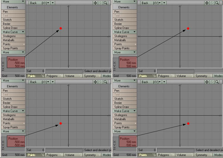
Picture 14: 4 different positions for the mouse pointer (Click to enlarge)
All of the views in picture 14 show the Back View (Bottom Left Viewport), and you can try this out yourself by just moving your mouse pointer in the Viewport.
There you have some information on how Modeler is built up and how things work in general. We will now start the main Tutorial, and while we go along we will do a few smaller tutorials on the tools we use etc.

0 commentaires:
Enregistrer un commentaire